
Punching equipment suitable for storage battery grid

A battery and punching technology, applied in metal processing equipment, punching tools, feeding devices, etc., can solve the problems of difficult to take out the grid, affect the punching range, and difficult to replace the punching die, and achieve a good punching effect. Effect

Active Publication Date: 2022-02-15
小洋电源股份有限公司
View PDF16 Cites 1 Cited by
  • Summary
  • Abstract
  • Description
  • Claims
  • Application Information

AI Technical Summary

Problems solved by technology

[0003] The punching position is not calibrated before punching the grid, there may be deviations that affect the punching effect, the bottom of the grid lacks a support buffer structure, it is easy to slide during punching, the position of the stamping die is not easy to adjust, and the punching range is affected, and There is no cutting structure on the equipment, it is not easy to trim the edge of the grid, the grid is not easy to take out on the limit structure, and the punching die is not easy to replace, which is not conducive to adjusting the size and shape of the punching hole

Method used


Image

  • Punching equipment suitable for storage battery grid
  • Punching equipment suitable for storage battery grid
  • Punching equipment suitable for storage battery grid

Examples


Embodiment Construction

[0027] In order to enable those skilled in the art to better understand the solution of the present application, the technical solution in the embodiment of the application will be clearly and completely described below in conjunction with the accompanying drawings in the embodiment of the application. Obviously, the described embodiment is only It is an embodiment of a part of the application, but not all of the embodiments. Based on the embodiments in this application, all other embodiments obtained by persons of ordinary skill in the art without creative efforts shall fall within the scope of protection of this application.

[0028] It should be noted that the terms "first" and "second" in the specification and claims of the present application and the above drawings are used to distinguish similar objects, but not necessarily used to describe a specific order or sequence. It should be understood that the data so used may be interchanged under appropriate circumstances for ...


PUM


Abstract

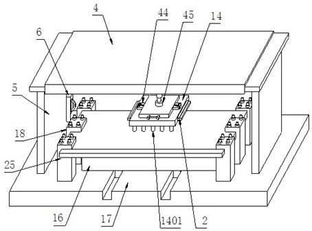
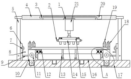
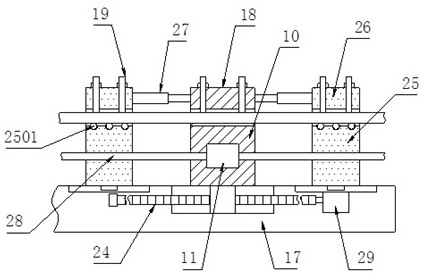
The invention discloses punching equipment suitable for a storage battery grid. The punching equipment comprises an operation table, a punching assembly and a limiting assembly. Supporting plates are fixedly connected to the top of the operation table, a transverse plate is fixedly connected to the tops of the two supporting plates, a punching assembly is installed at the bottom of the transverse plate and comprises a built-in plate, a stamping die and a hydraulic air cylinder, the built-in plate is connected to a first lead screw in a sleeving mode, and the first lead screw is connected into the transverse plate in a sleeving mode and rotatably connected with the transverse plate. A first motor is installed at the right end of the first lead screw, the built-in plate is in sliding connection with the transverse plate, a hydraulic air cylinder is fixedly connected to the bottom of the built-in plate, a stamping die is installed on the hydraulic air cylinder through a connecting plate, a recycling box is installed at the bottom of the stamping die, and the bottom of the recycling box is clamped to the operation table. The limiting assembly is installed on the top of the operation table. According to the punching equipment, the limiting range can be adjusted, the cutting function is achieved, and the punching effect is good.

Description

technical field [0001] The present application relates to a punching device, in particular to a punching device suitable for battery grids. Background technique [0002] The grid is the main component of the lead-acid battery. It is the current collector skeleton of the electrode, which plays the role of conducting, collecting and making the current evenly distributed. At the same time, it supports the active material and is the carrier of the active material. [0003] The punching position is not calibrated before punching the grid, there may be deviations that affect the punching effect, the bottom of the grid lacks a support buffer structure, it is easy to slide during punching, the position of the stamping die is not easy to adjust, and the punching range is affected, and There is no cutting structure on the equipment, it is not easy to trim the edge of the grid, the grid is not easy to take out from the limit structure, and the punching die is not easy to replace, which...

Claims


Application Information

Patent Timeline
Patent Type & Authority Applications(China)
IPC IPC(8): B21D28/26B21D28/34B21D28/04B21C51/00B21D43/20B21D43/28
CPCB21D28/26B21D28/34B21D28/04B21C51/00B21D43/20B21D43/287
Inventor 朱小平徐桂佳赵延安刘记曹胜基
Owner 小洋电源股份有限公司
Learn More