Electric jack for vehicle

A jack, electric technology, applied in the direction of vehicle maintenance, workshop equipment, transmission, etc., can solve the problem that the jack does not have a lifting unit, and the vehicle cannot be jacked or lifted.

Inactive Publication Date: 2004-03-03
沈钟煜
View PDF1 Cites 2 Cited by
  • Summary
  • Abstract
  • Description
  • Claims
  • Application Information

AI Technical Summary

Problems solved by technology

However, the above-mentioned jack does not have any device that allows the user to freely adjust the stroke of the lifting unit, so this jack cannot lift or lift the vehicle to the required large height when required

Method used


Image

  • Electric jack for vehicle
  • Electric jack for vehicle
  • Electric jack for vehicle

Examples


Embodiment Construction

[0022] Reference is now made to the drawings in which identical or similar parts are labeled with the same reference numerals throughout the various figures.

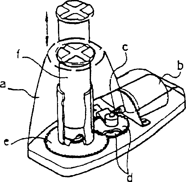
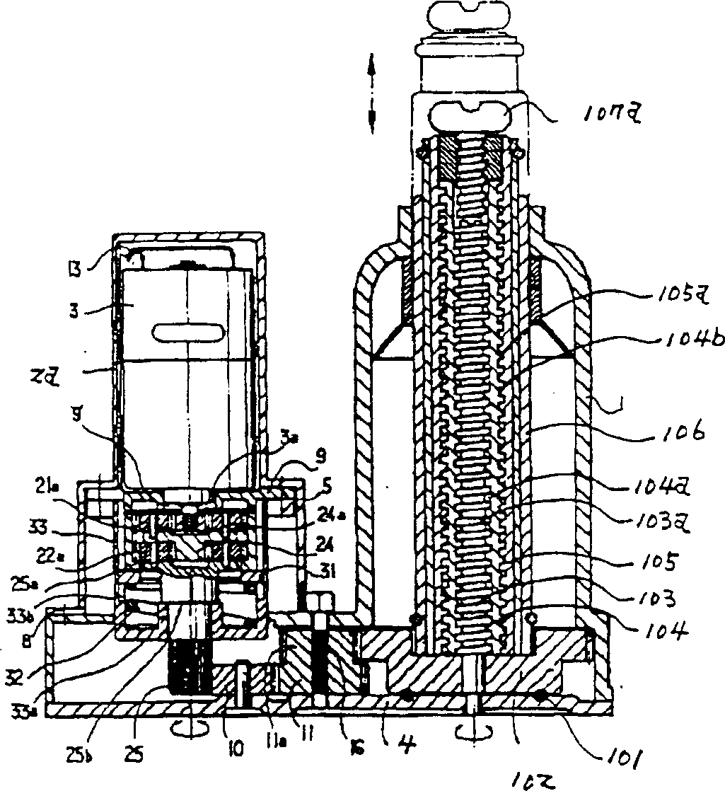
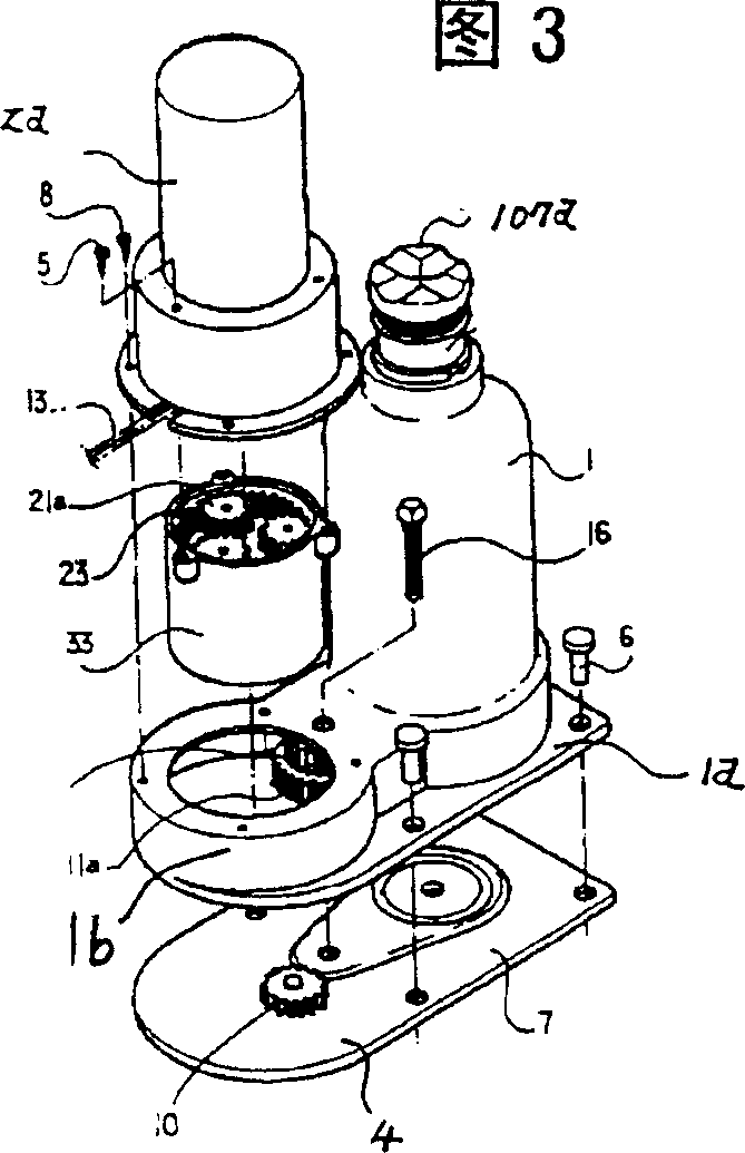
[0023] Fig. 3 is an exploded perspective view of an electric jack according to a preferred embodiment of the present invention. As shown, the jack of the present invention has a unitary body. The overall body includes a lifting unit casing 1 with a base flange 1a at its lower end. A lifting unit is housed in the lifting unit casing 1 . The power transfer unit is located in the bottom of the lifting unit casing 1 . An annular casing 1b is formed on the bottom side of the lifting unit casing 1, and this annular casing 1b is combined with the lifting unit casing 1 to form a structure. Installed on the base flange 1a, the bottom of the jack is closed. The motor casing 2a is segmented cylindrical and is vertically placed in the annular casing 1b. The lower part of the motor casing 2a with a large radius is located in the...


PUM


Abstract

A motor-operated jack for vehicles is disclosed. In the motor-operated jack of this invention, a lifting unit consists of a spiral lifting ram (105) having an internal thread (105a) limitedly formed at a lower portion of the spiral lifting ram (105), thus reducing its frictional resistance. A pin (103c) is held in a horizontal groove (103b) formed at the top end of a primary screw (103). This pin (103c) is slightly projected into two longitudinal holes (104c) symmetrically formed at the top portion of a secondary screw (104). A coil spring (103d), a spring cover (103e) and a snap ring (103f) are sequentially laid on the top of the pin (103c) such that the snap ring (103f) is seated in an annular groove (104d) formed on the inner surface of the top wall of the secondary screw (104), thus allowing the coil spring (103d) to bias the (103c) pin. This second screw (104) is thus prevented from being raised along with the spiral lifting ram (105). A support ram (107), having a top support (107a) and an external thread (107b), is movably fitted in a gap between the secondary screw (104) and the spiral lifting ram (105) while engaging with an internal thread (105c) of the spiral lifting ram (105) at the external thread (107b), thus allowing a user to control the moving stroke of the lifting unit as desired.

Description

technical field [0001] The invention relates to an electric jack for lifting or lifting a vehicle to a required height, in particular to an electric jack, which consists of a power transmission unit and a lifting unit, and its design purpose is to reduce the The unnecessary power consumption caused by the frictional resistance formed at the engaging thread joint, which consists of a device that can reliably make the screw lifting column lift ahead of the secondary screw when operating the jack, and a device that allows the user to adjust the lifting unit at will The device of the stroke. Background technique [0002] In the prior art, the jacks used to lift or lift the vehicle can be divided into the following categories: screw jacks, rack jacks, pneumatic or hydraulic jacks and electric jacks. In recent years, several electric jacks have been proposed and widely used. An example of such a conventional electric jack can be found in US Pat. No. 4,609,179. [0003] The stru...

Claims


Application Information

Patent Timeline
Patent Type & Authority Patents(China)
IPC IPC(8): B60S9/08B66F3/10B66F3/44
CPCF16H25/2056Y10S254/04F16H25/205B66F3/44B66F3/10B60S9/08
Inventor 沈钟煜
Owner 沈钟煜
Why Eureka
Try Eureka