Combined surveying and mapping device capable of being positioned and adjusted
A technology for surveying and mapping devices and positioning adjustment, which is applied in the direction of surveying devices, surveying and mapping and navigation, and measuring instruments, etc. It can solve problems such as inaccuracy and tilted test data of surveying and mapping devices, and achieve the goal of not being easily damaged, lowering the center of gravity, and improving the level of self-adaptive adjustment Effect
- Summary
- Abstract
- Description
- Claims
- Application Information
AI Technical Summary
Problems solved by technology
Method used
Image
Examples
Embodiment 1
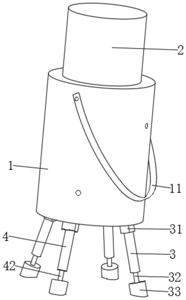
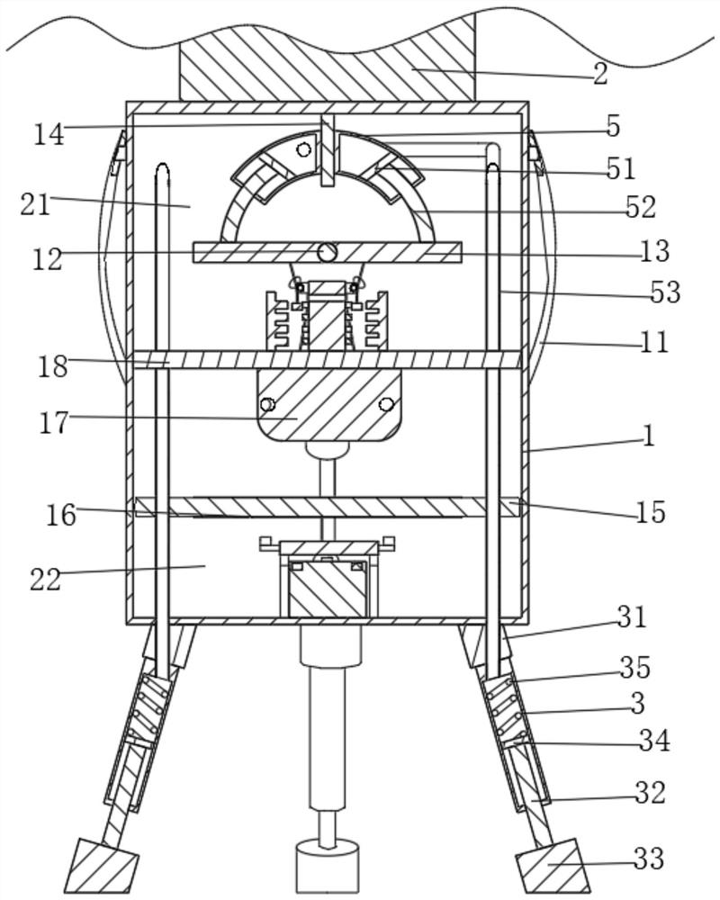
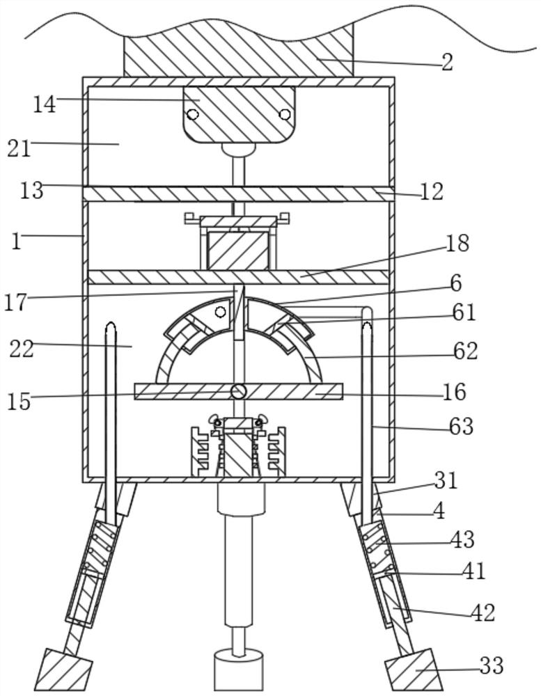
[0028] The present invention provides a technical solution: a combined modulating device, including housings 1 and the measuring plate, and the surveyor 2 is fixedly attached to the upper surface of the housing 1, and the inner wall of the housing 1 is fixedly connected to the load plate. 18. The housing 1 is divided into the first cavity 21 and the second cavity 22 by the load plate 18, and the first cavity 21 and the second cavity 22 are rotated and connected to the first rotational rod 12 and the second rotating rod. 15. The first rotating rod 12 and the arcuate contour of the second rotational rod 15 are fixed to the first support plate 13 and the second support plate 16, and the first cavity 21 and the second cavity 22 are fixed. The first connecting plate 14 and the second connecting plate 17, the first connecting plate 14 and the second connecting plate 17 are provided with an adjustment mechanism for adaptive adjustment of the mapping apparatus level.
[0029] See figure 1...
Embodiment 2
[0044] As in the example, further, the first cavity 21 and the second cavity 22 are provided with a reduced weight reduction mechanism for reducing the center of gravity of the measuring device, and the centering center of gravity includes a fixed connection in the first cavity 21, respectively. And the first pressure sensitive switch group 8 and the second pressure sensitive switch group 81 on the second cavity 22, each of the first pressure switch group 8 and the second pressure sensitive switch group 81 are arranged in linear arrangement. Sensitive switches, the first cavity 21 fixedly connected to two first electromagnet sets 7 of the first pressure switch group 8, each of which is provided with a pressure sensitive switch on each of the first electromagnet sets 7. The corresponding electromagnet, the second cavity 22 fixedly connected to two second electromagnet sets 9 on both ends of the second pressure sensitive switch group 81, each having a pressure sensitive switch on ea...
Embodiment 3
[0050] As in the first or two of the examples, further, the first rotational roller 73 and the second rotating roller 93 are provided with auxiliary mechanism for adjusting the secondary adjustment of the mechanism, and the auxiliary mechanism includes four first semi-circular blocks 74 and Four second semi-circular blocks 94, each two first semi-circular blocks 74 are fixed to both ends of each of the first rotational rollers 73, respectively, each of which is fixed to each second rotation roller 93, respectively. At both ends.
[0051] See figure 2 , image 3 , Figure 5 and Image 6 When the first iron block 76 is down, since the first drawstring rope 75 is surrounded on the first rotational roller 73 such that the first rotational roller 73 is rotated, since the first half round block is fixed to both ends of the first rotational roller 73 74 and the third support plate 72 fixedly coupled to the load plate 18 by the first flexible shrapnel 71 such that the third support plate 72 ...
PUM
 Abstract
Description
Claims
Application Information
 - R&D
- Intellectual Property
- Life Sciences
- Materials
- Tech Scout
- Unparalleled Data Quality
- Higher Quality Content
- 60% Fewer Hallucinations
Browse by: Latest US Patents, China's latest patents, Technical Efficacy Thesaurus, Application Domain, Technology Topic, Popular Technical Reports.
© 2025 PatSnap. All rights reserved.Legal|Privacy policy|Modern Slavery Act Transparency Statement|Sitemap|About US| Contact US: help@patsnap.com


