
Rural LED street lamp control circuit

A technology of LED street lights and control circuits, applied in the direction of energy-saving control technology, electrical components, etc., can solve problems such as waste of resources, and achieve the effect of saving resources

Pending Publication Date: 2022-02-15
张荣
View PDF0 Cites 0 Cited by
  • Summary
  • Abstract
  • Description
  • Claims
  • Application Information

AI Technical Summary

Problems solved by technology

[0004] In order to overcome the disadvantage that there are almost no pedestrians on the road in the middle of the night, but the street lights are still on, which is a waste of resources. The technical problem to be solved is: to provide a rural LED street light control circuit that can save resources.

Method used


Image

  • Rural LED street lamp control circuit
  • Rural LED street lamp control circuit

Examples


Embodiment 1

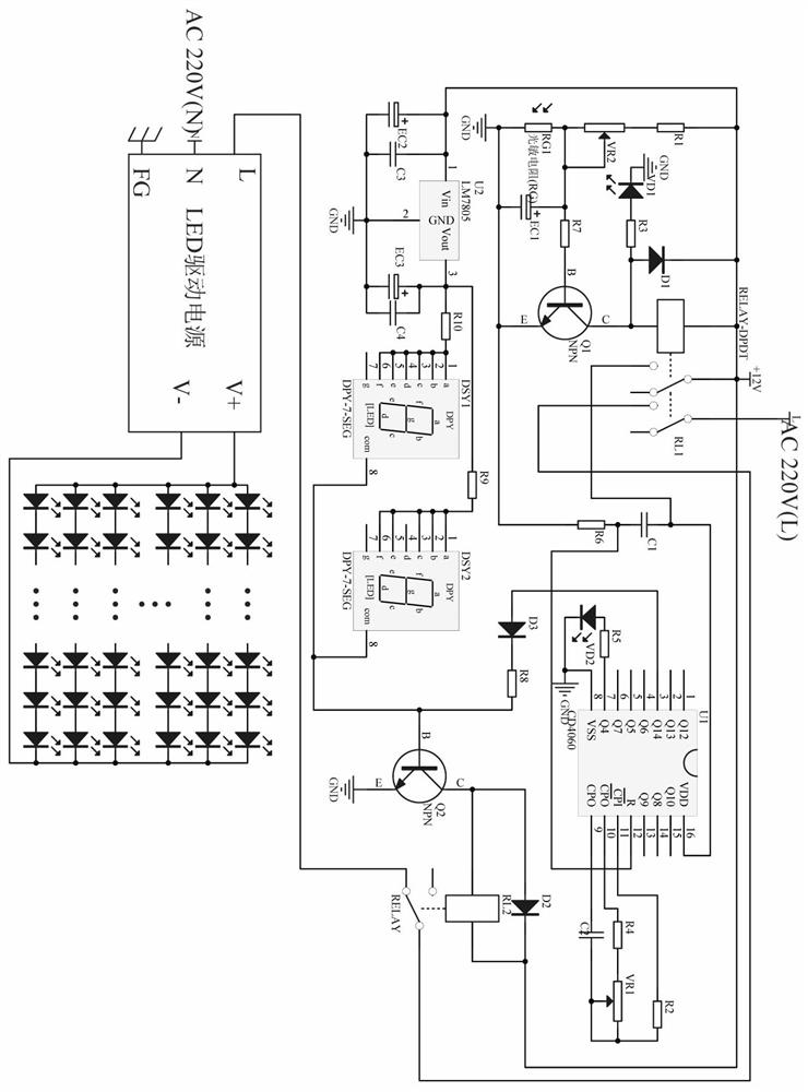
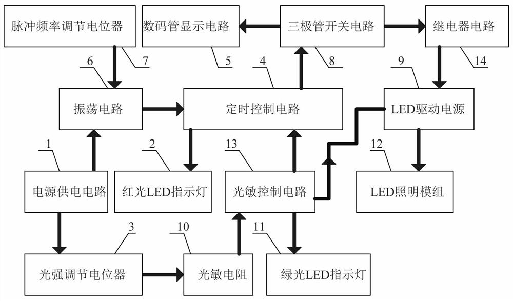
[0021] A rural LED street lamp control circuit, such as figure 1 As shown, it includes power supply circuit 1, red LED indicator light 2, light intensity adjustment potentiometer 3, timing control circuit 4, oscillation circuit 6, pulse frequency adjustment potentiometer 7, transistor switch circuit 8, LED drive power supply 9, Photoresistor 10, green LED indicator light 11, LED lighting module 12, photosensitive control circuit 13 and relay circuit 14, the output end of described red light LED indicator light 2 and timing control circuit 4 is connected, and described pulse frequency adjusts electric potential The device 7 is connected to the input end of the oscillating circuit 6, the output end of the oscillating circuit 6 is connected to the input end of the timing control circuit 4, the output end of the timing control circuit 4 is connected to the input end of the triode switch circuit 8, and the The output end of the triode switch circuit 8 is connected to the input end ...

Embodiment 2

[0026] A rural LED street lamp control circuit, such as figure 2 As shown, the timing control circuit 4 includes a 14-bit binary serial counter CD4060-U1, a resistor R5 and a light-emitting diode VD2, the 8 pins of the 14-bit binary serial counter CD4060-U1 are grounded, and the 14-bit binary serial counter The 7-pin of the row counter CD4060-U1 is connected in series with the resistor R5 and the anode of the light emitting diode VD2, and the cathode of the light emitting diode VD2 is grounded.

[0027] The oscillation circuit 6 includes a capacitor C2, a resistor R2 and a resistor R4, the 9-pin series capacitor C2 and the resistor R2 of the 14-bit binary serial counter CD4060-U1, the other end of the resistor R2 and the 14-bit binary serial Pin 11 of the counter CD4060-U1 is connected, and pin 10 of the 14-bit binary serial counter CD4060-U1 is connected to one end of the resistor R4.

[0028] The pulse frequency adjusting potentiometer 7 is a potentiometer VR1, the other e...


PUM


Abstract

The invention relates to LED illumination, in particular to a rural LED street lamp control circuit. The technical problem to be solved is to provide a rural LED street lamp control circuit capable of saving resources. The rural LED street lamp control circuit comprises a power supply circuit, a red light LED indicating lamp, a light intensity adjusting potentiometer, a timing control circuit, an oscillating circuit and the like. The red light LED indicating lamp is connected with the output end of the timing control circuit, and the pulse frequency adjusting potentiometer is connected with the input end of the oscillating circuit. The LED lighting module can be timed through the timing control circuit, the working time of the LED lighting module can be controlled, the LED lighting module can be controlled to be turned off at night, resources are saved, and the state of the LED lighting module can be indicated through a nixie tube display circuit.

Description

technical field [0001] The invention relates to LED lighting, in particular to a rural LED street lamp control circuit. Background technique [0002] Street lamp is a lamp that can automatically light up at night to provide illumination for pedestrians. It is generally installed on both sides of the road. Street lamps are generally light-controlled. When the light is dark, the street lamp automatically lights up. The street lights are automatically turned off. In the middle of the night, there are almost no pedestrians on the road, but the street lights are still on, which is a waste of resources. [0003] Therefore, there is a special need for a rural LED street lamp control circuit that can save resources, so as to solve the existing problems. Contents of the invention [0004] In order to overcome the disadvantage that there are almost no pedestrians on the road in the middle of the night, but the street lights are still on, which is a waste of resources, the technical...

Claims


Application Information

Patent Timeline
Patent Type & Authority Applications(China)
IPC IPC(8): H05B45/00H05B45/12H05B47/16H05B47/11
CPCH05B45/00H05B45/12H05B47/16H05B47/11Y02B20/40
Inventor 张荣
Owner 张荣
Learn More