Medical clinical examination device convenient to operate

An easy-to-operate, medical technology, applied in the field of medical clinical examination, can solve problems such as discomfort, the large angle between the patient's upper body and legs, and inconvenience to patients

Pending Publication Date: 2022-02-18
淄川区太河中心卫生院
View PDF0 Cites 1 Cited by
  • Summary
  • Abstract
  • Description
  • Claims
  • Application Information

AI Technical Summary

Problems solved by technology

[0005] Aiming at the deficiencies of the prior art, the present invention provides a conveniently operated medical clinical examination device, which solves the inconvenience of medical clinical examination, such as expanding the oral cavity of patients with different mouth wi

Method used


Image

  • Medical clinical examination device convenient to operate
  • Medical clinical examination device convenient to operate
  • Medical clinical examination device convenient to operate

Examples


Embodiment 1

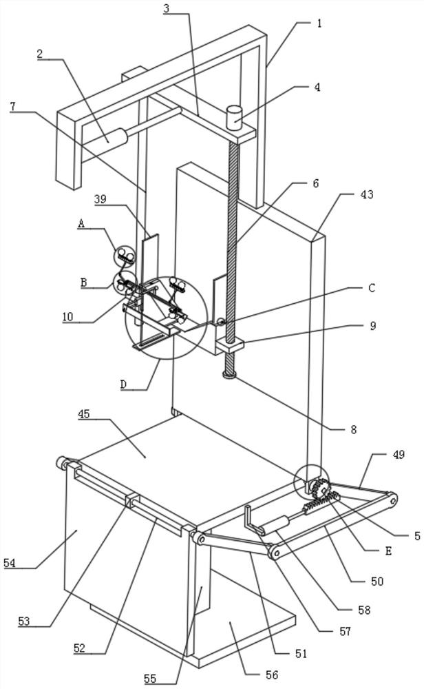
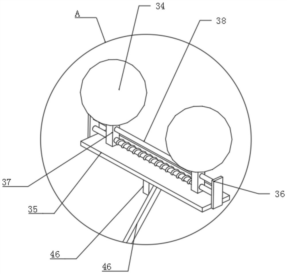
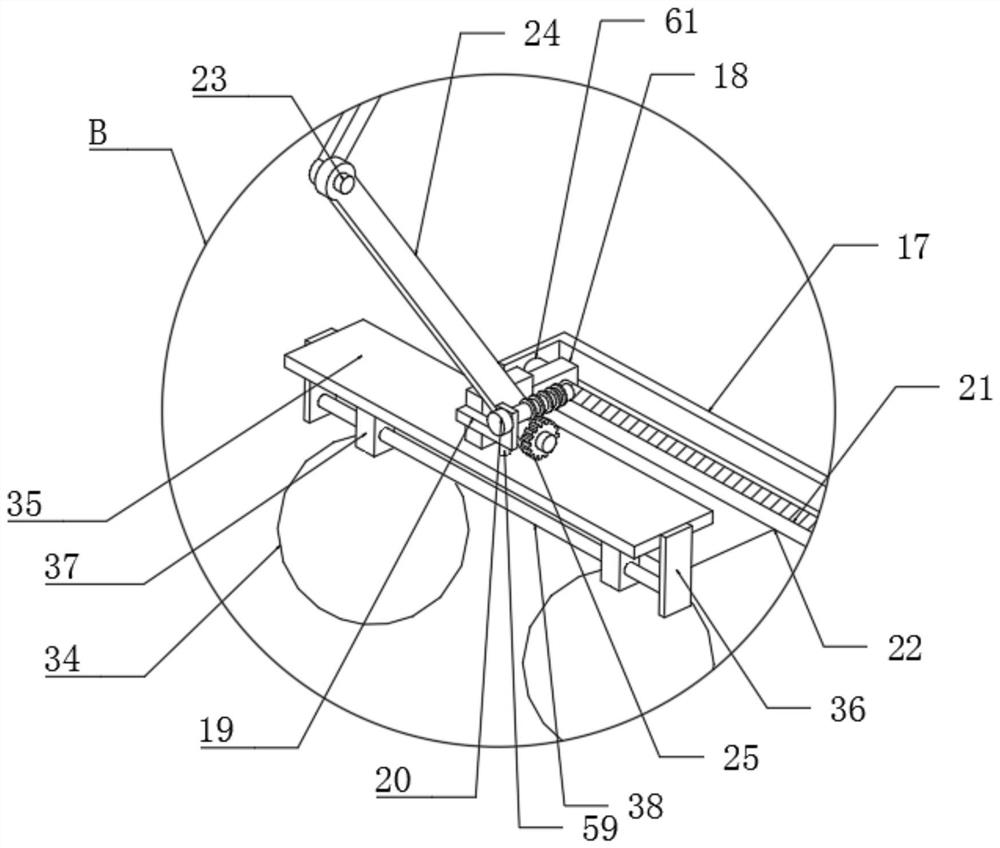
[0031]Embodiment 1: An easy-to-operate medical clinical inspection device, including a mounting plate 1, a backing plate 43 is fixedly connected to the lower end surface of the rear side of the mounting plate 1, and a first electric telescopic device is fixedly connected to the middle part of the lower end of the inner front surface of the mounting plate 1 Rod 2, the output end of the first electric telescopic rod 2 is fixedly connected to the traverse plate 3, the upper end of the traverse plate 3 is fixedly connected to the right side of the first motor 4, and the output end of the first motor 4 is fixedly connected to the first threaded rod 6, The left side of the lower end surface of the traversing plate 3 is fixedly connected with a first slide bar 7 , the first slide bar 7 is slidably connected with a lifting block 10 outside, and the first threaded rod 6 is externally threaded with a first thread block 9 . The end faces of the lifting block 10 and the first threaded bloc...

Embodiment 2

[0033] Embodiment two: the difference between this implementation and embodiment one is that, wherein, the left side of the V-shaped block 26 is provided with a groove 32, and the upper and lower ends of the groove 32 are rotatably connected with a second threaded rod 27, and the second threaded rod 27 external threads are connected with a second threaded block 28, the rear end of the second threaded block 28 is slidingly connected with a groove 32, the upper side of the front end of the second threaded rod 27 is fixedly connected with a third sliding rod 33, and the front end of the second threaded rod 27 is The lower side is rotatably connected with a third threaded rod 29, the third threaded rod 29 is externally threaded with an offset plate 30, the third slide bar 33 is slidably connected with an offset plate 30, and the right side of the rear end surface of the offset plate 30 is fixedly connected with a press. Tongue plate 31. The left and right sides of the lower end su...


PUM


Abstract

The invention discloses a medical clinical examination device convenient to operate. The medical clinical examination device comprises a mounting plate, wherein a backup plate is fixedly connected to the lower end face of the rear side of the mounting plate, a first electric telescopic rod is fixedly connected to the middle of the lower end of the front end face of the inner side of the mounting plate, a transverse moving plate is fixedly connected to the output end of the first electric telescopic rod, a first motor is fixedly connected to the right side of the upper end face of the transverse moving plate, a first threaded rod is fixedly connected to the output end of the first motor, a lifting block is slidably connected to the exterior of the first sliding rod, and a first threaded block is in threaded connection to the exterior of the first threaded rod. The invention relates to the technical field of medical clinical examination. According to the medical clinical examination device convenient to operate, the problems that oral cavities of patients with different mouth widths and different tooth shapes are inconvenient to expand, heads of patients with different heights and different head widths are inconvenient to fix, and discomfort is caused due to the fact that a large included angle is formed between the upper body and the legs of the patients in medical clinical examination are solved.

Description

technical field [0001] The invention relates to the technical field of medical clinical examination, in particular to a conveniently operated medical clinical examination device. Background technique [0002] Teeth are a part of the oral cavity. With the continuous innovation of medical equipment, people nowadays pay as much attention to the oral cavity as to their physical health. The oral cavity is the beginning part of the digestive tract. . In the treatment and nursing process of oral diseases, it is often necessary to keep the patient's mouth open for a long time. Usually, the upper and lower braces are used to cover the outside of the patient's upper and lower teeth, and then the upper and lower braces are separated from each other for expansion to open the patient's mouth. [0003] Existing medical clinical inspection devices that are convenient to operate have a limited scope of application, are inconvenient to adapt to patients with different mouth widths and tooth...

Claims


Application Information

Patent Timeline
IPC IPC(8): A61C19/04A61C19/00A61G15/00A61G15/10A61G15/12A61G15/14A61G15/02
CPCA61C19/00A61C19/04A61G15/02A61G15/10A61G15/12A61G15/125A61G15/14
Inventor 孙淑军
Owner 淄川区太河中心卫生院
Why Eureka
Try Eureka