Horizontal straightening machine

A straightening machine, horizontal technology, applied in the field of straightening machines, can solve the problems of low correction ability, complicated operation, low degree of automation, etc., and achieve the effect of large correction ability and wide adaptability

Pending Publication Date: 2022-02-18
NINGBO JINFENG WELDING & CUTTING MACHINERY MFR
View PDF0 Cites 0 Cited by
  • Summary
  • Abstract
  • Description
  • Claims
  • Application Information

AI Technical Summary

Problems solved by technology

[0002] With the increasing demand for welded H-shaped steel in the steel structure industry, how to improve production efficiency has become the key for manufacturers to win the market. Since the H-shaped steel flange is heated during the welding process, it will cause its deformation. Therefore, the flange of the H-shaped steel needs to be welded. Correction, there are two types of H-shaped steel straightening machines, one is to correct the single-sided wing plate, and the other is to correct the two-sided wing plates at the same time. The above two straightening machines start from placing the H-shaped steel on the roller table, and the accuracy Detection and correction parameter setting all require manual participation, low degree of automation, cumbersome operation, and low production efficiency. At the same time, the existing straightening machines generally adopt the middle support and two-side extrusion correction method. The correction ability of this structure is relatively low. Correction of H-shaped steel flanges that are not suitable for both thick and narrow flanges

Method used


Image

  • Horizontal straightening machine
  • Horizontal straightening machine
  • Horizontal straightening machine

Examples


Embodiment Construction

[0027] The present invention will be further described below in conjunction with the accompanying drawings.

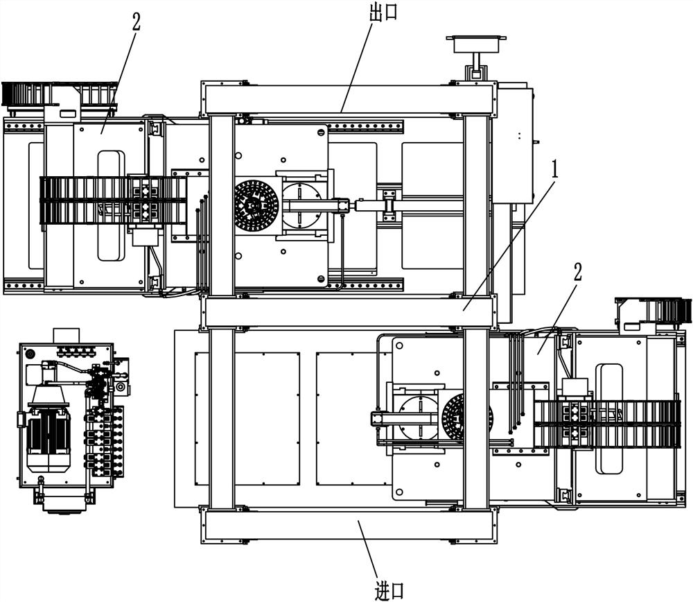
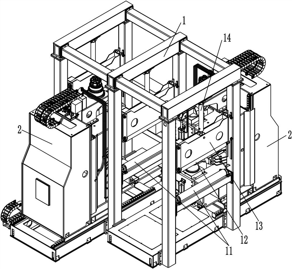
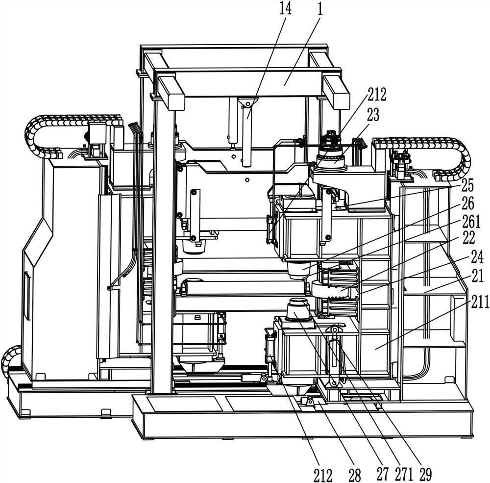
[0028] Such as Figure 1-6 As shown, a horizontal straightening machine includes a fixed frame 1 and straightening devices 2 arranged on both sides of the fixed frame 1. The fixed frame 1 is provided with an inlet and an outlet for materials (H-shaped steel) to pass through. The fixed The support roller table 11 is provided on the frame 1, and the support roller table 11 is composed of at least two rollers arranged at intervals, and the rollers are rotatably connected to the fixed frame 1 through bearings, so that the rollers can rotate freely along their axis of rotation. The fixed frame 1 is provided with a pressure roller 12 that can be vertically lifted at the position corresponding to the upper end of the supporting roller table 11. Specifically, the fixed frame 1 is provided with a slide plate 13 that can slide up and down along the fixed frame 1. The slide plate...


PUM


Abstract

The invention discloses a horizontal straightening machine which comprises a fixing frame and straightening devices arranged on the two sides of the fixing frame, a supporting roller way and a pressing roller are arranged on the fixing frame; the straightening device comprises a machine body, a straightening wheel, a first driving device and a second driving device; the first driving device is connected to the machine body through a universal coupling, the first driving device is connected to the correcting wheel and used for driving the straightening wheel to rotate, or the first driving device is fixed to the machine body, and the first driving device is connected to the straightening wheel through the universal coupling; the second driving device drives the straightening wheel to transversely move so as to correct the wing plate; an upper supporting piece and a lower supporting piece which are located on the upper side and the lower side of the straightening wheel are arranged on the machine body, the lower supporting piece is correspondingly arranged on the lower portion of the upper supporting piece, the two supporting pieces are arranged on the other side, opposite to the second driving device, of the straightening wheel, and a channel for a wing plate to penetrate through is reserved between the straightening wheel and the two supporting pieces. The straightening quality of the straightening machine is good, and meanwhile, the correction efficiency and the automation degree are high.

Description

technical field [0001] The invention relates to the technical field of straightening machines, in particular to a horizontal straightening machine. Background technique [0002] With the increasing demand for welded H-shaped steel in the steel structure industry, how to improve production efficiency has become the key for manufacturers to win the market. Since the H-shaped steel flange is heated during the welding process, it will cause its deformation. Therefore, the flange of the H-shaped steel needs to be welded. Correction, there are two types of H-shaped steel straightening machines, one is to correct the single-sided wing plate, and the other is to correct the two-sided wing plates at the same time. The above two straightening machines start from placing the H-shaped steel on the roller table, and the accuracy Detection and correction parameter setting all require manual participation, low degree of automation, cumbersome operation, and low production efficiency. At th...

Claims


Application Information

Patent Timeline
Patent Type & Authority Applications(China)
IPC IPC(8): B21D3/02B21D43/00
CPCB21D43/003B21D3/02
Inventor 黄金彪章德均黄凯凯沈立幸
Owner NINGBO JINFENG WELDING & CUTTING MACHINERY MFR
Why Eureka
Try Eureka