
Stamping equipment for battery poles

A technology for stamping equipment and batteries, applied in metal processing equipment, feeding devices, manufacturing tools, etc., can solve problems such as reducing stamping efficiency, affecting processing efficiency, and difficult to achieve tight fit, improving stamping efficiency and ensuring processing efficiency. , The effect of convenient transportation

Active Publication Date: 2022-04-15
小洋电源股份有限公司
View PDF1 Cites 0 Cited by
  • Summary
  • Abstract
  • Description
  • Claims
  • Application Information

AI Technical Summary

Problems solved by technology

[0003] In the patent document "Stamping device for CN201721098795.X terminal pole", in the stamped terminal pole, the density of the lead jacket is higher, and the contact fit between the copper core and the lead jacket is better, which improves the Electrical conductivity, and can effectively improve the torsion resistance after the glue and the terminal post are bonded, but the stamping effect is poor. Only relying on the first hydraulic cylinder and the second hydraulic cylinder to realize the stamping between the copper core and the lead jacket, it is difficult to achieve a tight fit At the same time, the lead used in pole processing is a toxic metal, and it is difficult to achieve integrated transportation during loading and unloading. At the same time, the processing steps are relatively complicated, and manual intervention may be required for processing, which not only reduces stamping efficiency, but also affects The health of the operator, and the inconvenient connection between the pole and the terminal affect its processing efficiency
At present, there is no stamping equipment suitable for battery poles with reasonable and reliable structure, high-efficiency stamping function and safe operation performance.

Method used


Image

  • Stamping equipment for battery poles
  • Stamping equipment for battery poles
  • Stamping equipment for battery poles

Examples


Embodiment Construction

[0031] In order to enable those skilled in the art to better understand the solution of the present application, the technical solution in the embodiment of the application will be clearly and completely described below in conjunction with the accompanying drawings in the embodiment of the application. Obviously, the described embodiment is only It is an embodiment of a part of the application, but not all of the embodiments. Based on the embodiments in this application, all other embodiments obtained by persons of ordinary skill in the art without creative efforts shall fall within the scope of protection of this application.

[0032] It should be noted that the terms "first" and "second" in the description and claims of the present application and the above drawings are used to distinguish similar objects, but not necessarily used to describe a specific sequence or sequence. It should be understood that the data so used may be interchanged under appropriate circumstances for...


PUM


Abstract

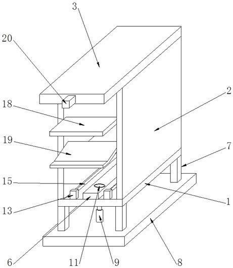
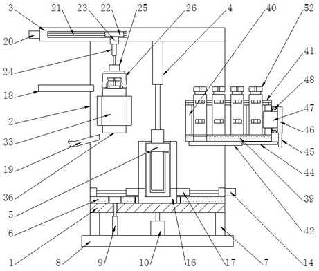
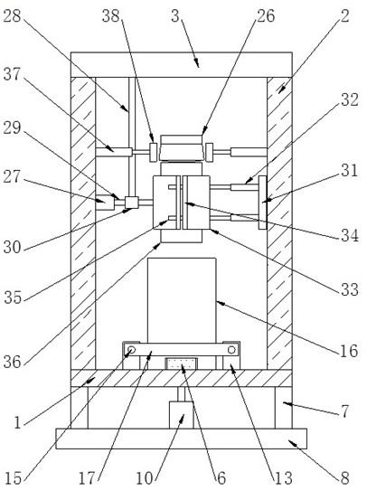
This application belongs to the technical field of battery poles. This application discloses stamping equipment suitable for battery poles, including worktables, vertical plates, top plates, stamping hydraulic cylinders, stamping heads, guide rails, legs, bases, jacking cylinders, rotating Motor, top block, cross bar, fixed block, travel motor, lead screw, mold base, fixed plate, loading plate, unloading plate, conveying motor, threaded rod, slider, adjusting motor, lifting cylinder, negative pressure suction cup, Pole end, feeding motor, vertical rod, drive shaft, bearing, turntable, electric push rod, splint, flange, guide rod, lead cover, first hydraulic cylinder, first pressure head, conveying plate, side plate , guide plate, baffle plate, limit plate, connecting rod, connecting plate, push plate, push block, spring, mounting plate, second hydraulic cylinder, second pressure head, copper core, groove, terminal, notch, guide groove , sinks and openings. In the present application, by adopting a lead-wrapped pole with a copper core, the stamping and forming of the lead-cover and the copper core and the end of the pole is realized.

Description

technical field [0001] The invention specifically relates to stamping equipment suitable for battery poles, and belongs to the technical field of battery poles. Background technique [0002] The battery pole is a part that is directly connected to the bus bar at one end, and the other end is connected to the external conductor, or to one pole of the adjacent single battery in the battery pack. Commonly used batteries include: lead-acid batteries, nickel-cadmium batteries, Iron-nickel batteries, zinc-silver batteries, zinc-nickel batteries, hydrogen-nickel batteries, lithium-ion batteries, different battery pole materials are not the same, the common one is lead, and it can also be electroplated with brass, or copper, or directly made of copper. Pole, UPS backup power supply, large battery is mostly made of copper material electroplating as pole, UPS small battery is mostly electroplated with copper sheet. [0003] In the patent document "Stamping device for CN201721098795.X...

Claims


Application Information

Patent Timeline
Patent Type & Authority Patents(China)
IPC IPC(8): B21D22/02B21D43/18
CPCB21D22/02B21D43/18
Inventor 朱小平徐桂佳赵延安刘记曹胜基
Owner 小洋电源股份有限公司
Learn More