High-pressure oil pump top dead center position self-learning method, rail pressure control method, vehicle controller and vehicle

A self-learning method and vehicle controller technology, applied in the engine field, can solve the problem of inaccurate calculation of the real-time position of the top dead center of the oil pump, etc.

Active Publication Date: 2022-02-18
GREAT WALL MOTOR CO LTD
View PDF15 Cites 0 Cited by
  • Summary
  • Abstract
  • Description
  • Claims
  • Application Information

AI Technical Summary

Problems solved by technology

[0007] In view of this, the present invention aims to propose a self-learning method for the position of the top dead center of the high-pressure oil pump to solve the problem of inaccurate calculation of the real-time position of the top dead center of the oil pump at the present stage

Method used


Image

  • High-pressure oil pump top dead center position self-learning method, rail pressure control method, vehicle controller and vehicle
  • High-pressure oil pump top dead center position self-learning method, rail pressure control method, vehicle controller and vehicle
  • High-pressure oil pump top dead center position self-learning method, rail pressure control method, vehicle controller and vehicle

Examples


Embodiment 1

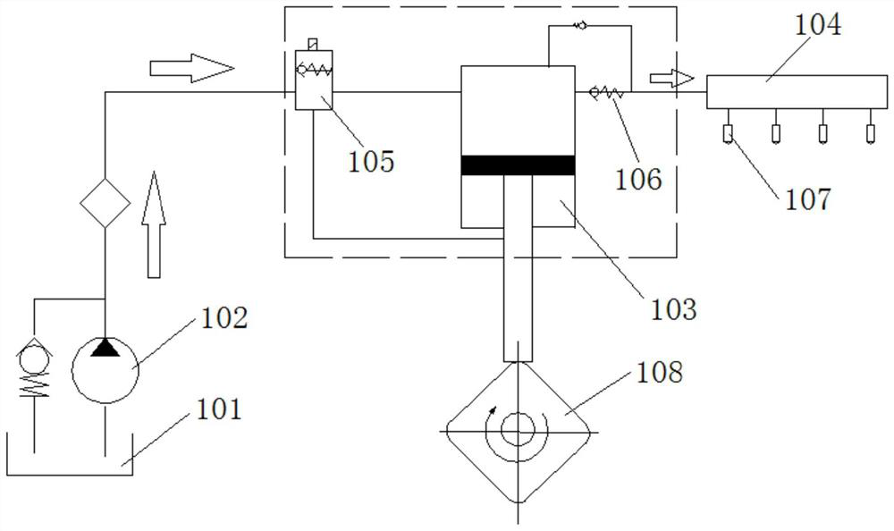
[0054] image 3 It is a schematic flow chart of the self-learning method for the top dead center position of the high-pressure oil pump in Embodiment 1 of the present invention. For the position and working principle of the high-pressure oil pump in the common rail system of the engine, please refer to figure 1 and Figure 2(a)-Figure 2(c) . from figure 1 It can be seen that the high-pressure oil pump 103 is arranged between the low-pressure oil circuit and the high-pressure oil circuit of the common rail system of the engine, and has a pressure regulating valve 105 that controls fuel to enter the high-pressure oil pump body through the low-pressure oil circuit. For the pressure regulating valve 105 , the MSV valve is used as an example below.

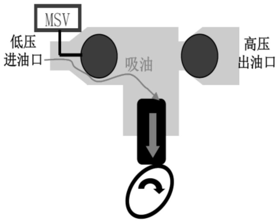
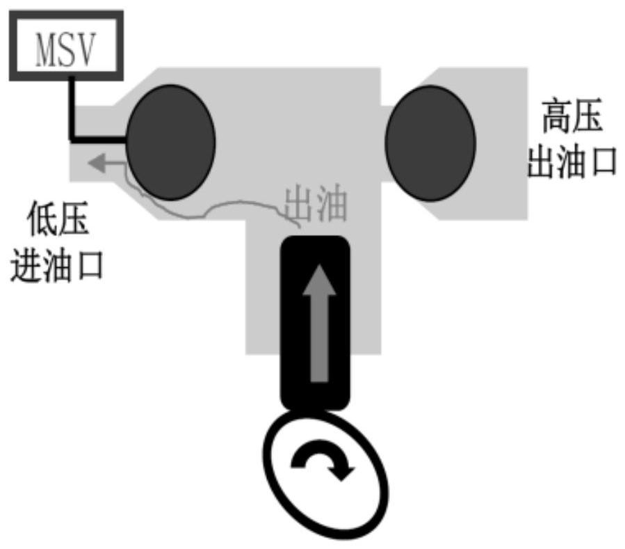
[0055] Figure 4 It is a schematic diagram of the principle of an example of self-learning the top dead center position of the high-pressure oil pump in the embodiment of the present invention, which is the same as Figure 1-Figur...

Embodiment 2

[0086] Image 6 It is a schematic flowchart of a method for controlling rail pressure of a high-pressure oil pump according to Embodiment 2 of the present invention. like Image 6 As shown, the high-pressure oil pump rail pressure control method may include the following steps:

[0087] In step S610, the top dead center position of the high pressure oil pump is determined using the above-mentioned self-learning method for the top dead center position of the high pressure oil pump.

[0088] Here, for the specific implementation details of step S610, reference may be made to Embodiment 1, which will not be repeated here.

[0089] Step S620, based on the determined top dead center position of the high-pressure oil pump, determine the closing time and closing duration of the pressure regulating valve.

[0090] Referring to Figure 2(c) and figure 1 , when the MSV valve is closed, the connection between the high-pressure oil pump 103 and the low-pressure oil circuit is cut off, ...


PUM


Abstract

The invention relates to the technical field of engines, and provides a high-pressure oil pump top dead center position self-learning method and a rail pressure control method. The method comprises the following steps: executing the following self-learning process: setting an initial oil pump top dead center position at a first position corresponding to a set angle before a theoretical bottom dead center; reducing the oil pump top dead center position from the first position, so that the pressure regulating valve moves towards the oil pump bottom dead center direction in the opening duration until the rail pressure corresponding to the high-pressure oil way is equal to the pressure in the low-pressure oil way, and the oil pump top dead center position at the moment is recorded as the oil pump bottom dead center position; and the recorded oil pump bottom dead center position and the angle corresponding to the oil pumping stroke are added, and the final oil pump top dead center position is obtained. According to the method, the more accurate oil pump top dead center position can be obtained, and more accurate rail pressure control can be achieved conveniently.

Description

technical field [0001] The invention relates to the technical field of engines, in particular to a method for self-learning the top dead center position of a high-pressure oil pump, a rail pressure control method, a vehicle controller and a vehicle. Background technique [0002] With the continuous improvement of our country's economic level, automobiles are gradually popularized in ordinary families, and energy and environmental issues have increasingly become the focus of people's attention. The gasoline direct injection (Gasoline Direct Injection, hereinafter referred to as GDI) gasoline engine, also known as the GDI engine, has become a research hotspot in major research institutions because of its advantages such as good power, good fuel economy, and low emissions. In addition, the GDI gasoline engine directly injects gasoline into the cylinder, which can precisely control the fuel injection volume and intake air volume, thereby adjusting the air-fuel ratio, and has goo...

Claims


Application Information

Patent Timeline
IPC IPC(8): F02M55/02F02M59/46
CPCF02M55/025F02M59/46Y02T10/40
Inventor 代沙沙张文贤邢化锋王文宾陈利明商璞左坤峰
Owner GREAT WALL MOTOR CO LTD
Why Eureka
Try Eureka