Uplink power control calculation method and equipment

A calculation method and terminal equipment technology, applied in the field of wireless communication, can solve problems such as inaccurate uplink power control calculation methods, achieve accurate calculation and solve the effect of inaccurate calculation

Active Publication Date: 2020-01-17
CHINA UNITED NETWORK COMM GRP CO LTD
View PDF10 Cites 1 Cited by
  • Summary
  • Abstract
  • Description
  • Claims
  • Application Information

AI Technical Summary

Problems solved by technology

[0005] Embodiments of the present application provide an uplink power control calculation method and device for solving the problem of inaccurate uplink power control calculation methods

Method used


Image

  • Uplink power control calculation method and equipment
  • Uplink power control calculation method and equipment
  • Uplink power control calculation method and equipment

Examples


Embodiment 1

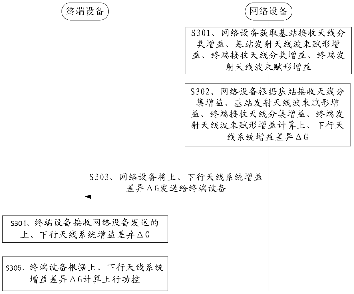
[0050] The embodiment of the present application provides an uplink power control calculation method, such as image 3 As shown in , the uplink power control calculation method includes:

[0051] S301. The network device acquires a base station receive antenna diversity gain, a base station transmit antenna beamforming gain, a terminal receive antenna diversity gain, and a terminal transmit antenna beamforming gain.

[0052] Antenna diversity gain, base station transmit antenna beamforming gain, terminal receive antenna diversity gain, and terminal transmit antenna beamforming gain are all obtained through preconfiguration. Wherein, the beamforming gain includes beamforming in multiple ways such as antenna selection and weight summation.

[0053] S302. The network device calculates an uplink and downlink antenna system gain difference ΔG according to the base station receive antenna diversity gain, the base station transmit antenna beamforming gain, the terminal receive anten...

Embodiment 2

[0093] The embodiment of this application provides a network device, such as Figure 5 As shown, the network device 500 includes: an acquisition unit 501 , a calculation unit 502 , and a sending unit 503 . The uplink power control calculation device is configured to execute the above-mentioned uplink power control calculation method. specific:

[0094] The obtaining unit 501 is configured to obtain a base station receive antenna diversity gain, a base station transmit antenna beamforming gain, a terminal receive antenna diversity gain, and a terminal transmit antenna beamforming gain.

[0095] The calculation unit 502 is configured to calculate the uplink and downlink antenna system gain difference ΔG according to the base station receive antenna diversity gain, base station transmit antenna beamforming gain, terminal receive antenna diversity gain, and terminal transmit antenna beamforming gain acquired by the acquiring unit 501.

[0096] Specifically, the calculation unit ...


PUM


Abstract

The invention discloses an uplink power control calculation method and device, relates to the field of wireless communication, and is used for uplink power control calculation. The uplink power control calculation method comprises the steps that network equipment acquires base station receiving antenna diversity gain, base station transmitting antenna beamforming gain, terminal receiving antenna diversity gain and terminal transmitting antenna beamforming gain; the network equipment calculates an uplink and downlink antenna system gain difference delta G according to the base station receivingantenna diversity gain, the base station transmitting antenna beamforming gain, the terminal receiving antenna diversity gain and the terminal transmitting antenna beamforming gain; the network device sends the uplink and downlink antenna system gain difference delta G to the terminal device; the terminal equipment receives the uplink and downlink antenna system gain difference delta G sent by the network equipment; and the terminal equipment calculates uplink power control according to the uplink and downlink antenna system gain difference delta G. The embodiment of the invention is appliedto uplink power control calculation.

Description

technical field [0001] The present application relates to the field of wireless communication, and in particular to an uplink power control calculation method and device. Background technique [0002] In the current uplink power control algorithm, the initial open-loop power control is based on estimating the downlink path loss (path loss, PL) of the user equipment (user equipment, UE). The UE performs downlink PL estimation by measuring the downlink reference signal receiving power (reference signal receiving power, RSRP) and subtracting it from the known reference signal power. [0003] In the 4th generation mobile communication technology (4G) network, the antenna of the 4G base station is basically 2 transmit modules (transmit, T) 2 receive modules (receive, R), 4T4R or 8T8R, the antenna of the 4G terminal It is basically 1T2R. Therefore, the difference in the number of antennas between the terminal and the base station in the 4G network is not large, and the gain of th...

Claims


Application Information

Patent Timeline
Patent Type & Authority Applications(China)
IPC IPC(8): H04W52/14H04W52/24
CPCH04W52/146H04W52/24
Inventor 刘光海李一龙青良肖天薛永备田元兵
Owner CHINA UNITED NETWORK COMM GRP CO LTD
Why Eureka
Try Eureka