Method for measuring displacement of oscillating piston

A piston displacement and measurement method technology, which is applied in measuring devices, radio wave measurement systems, and measuring ultrasonic/sonic/infrasonic waves, etc., can solve problems such as the inability to directly measure piston displacement, the inability to install sensors, and the inability to directly measure piston displacement.

Pending Publication Date: 2022-02-18
SHENYANG LIMING AERO-ENGINE GROUP CORPORATION
View PDF0 Cites 0 Cited by
  • Summary
  • Abstract
  • Description
  • Claims
  • Application Information

AI Technical Summary

Problems solved by technology

Since the piston is installed in the casing, it is necessary to ensure the sealing of the piston and the casing. The wall surface in contact between the piston and the casing cannot be damaged, and t

Method used


Image

  • Method for measuring displacement of oscillating piston
  • Method for measuring displacement of oscillating piston

Examples


Embodiment 1

[0020] The purpose of this embodiment is to propose a method for measuring the displacement of the oscillating piston, especially to provide a method for measuring the displacement of the high-frequency oscillating piston in the test of the aeroengine components without causing major damage to the casing.

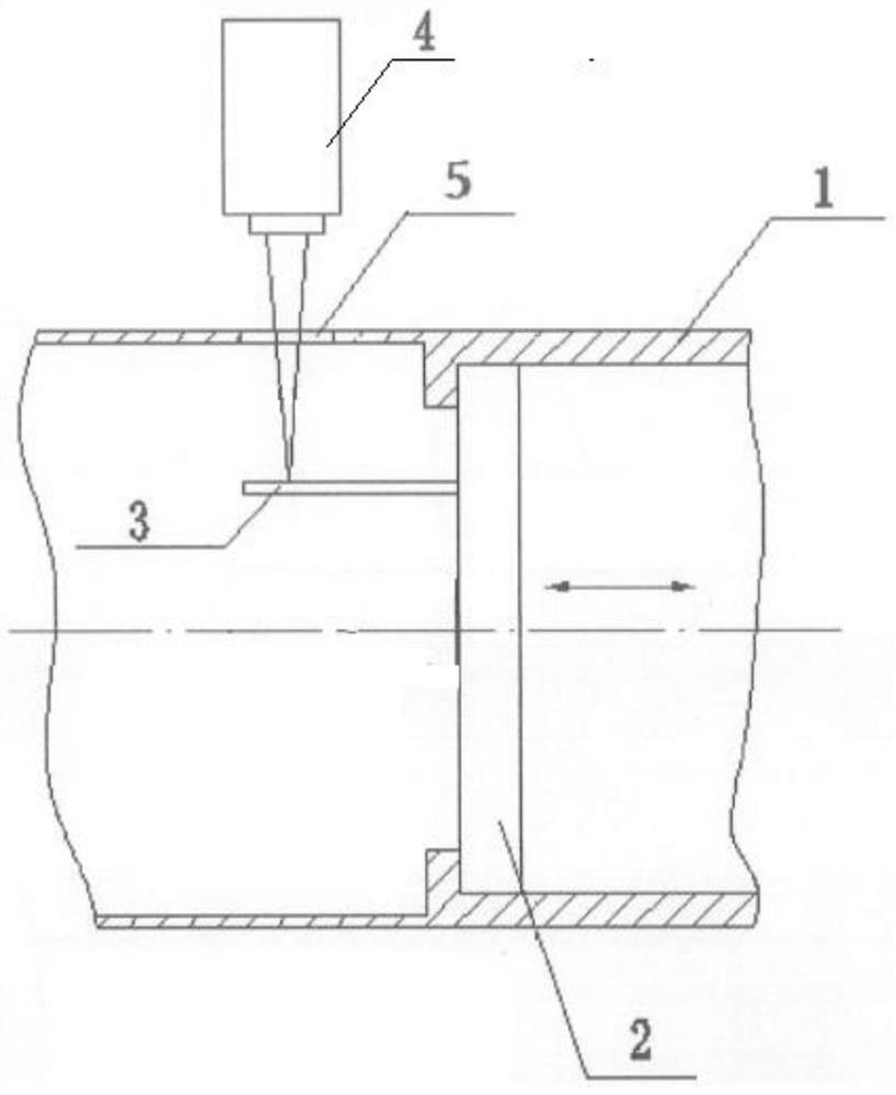
[0021] A method for measuring the displacement of an oscillating piston. Holes are opened in the non-working area of ​​the casing 1 perpendicular to the axial direction. After the holes are opened, light-transmitting glass 5 is filled in the gaps and sealed with sealant to ensure the tightness of the casing. Generally speaking, on the wall surface of the casing 1 apart from the working position of the piston 2 by 15 centimeters, a hole with a diameter of 4 cm is opened perpendicular to its axial direction.

[0022] On the non-working surface of the piston 2, use silica gel to fix the piston displacement lead-out part 3 perpendicular to the surface of the piston 2, and the pi...

Embodiment 2

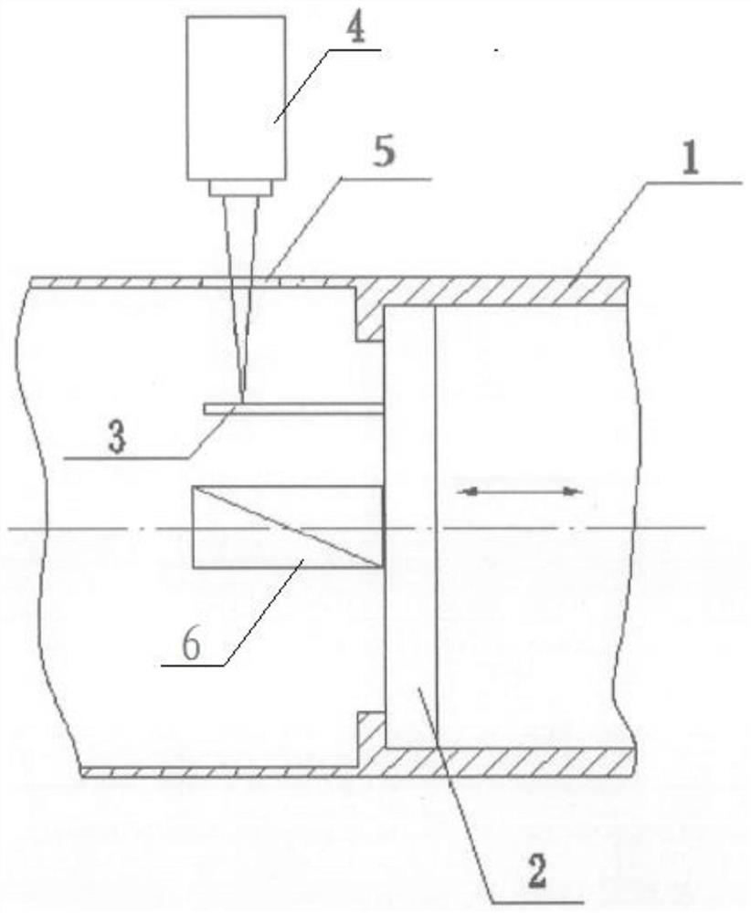
[0030] This example figure 2 As shown, the piston 2 is driven by the electromagnet 6, and the laser beam emitted by the laser vibrometer 4 is irradiated on the piston outlet 3 through the transparent glass 5. By testing the displacement of the piston outlet 3, the oscillation displacement of the piston 2 can be obtained. quantity.

[0031] The remaining implementation methods and expected effects are the same as in Example 1.


PUM


Abstract

The invention relates to a method for measuring the displacement of an oscillation piston. The method comprises the steps that: a hole is formed in a non-working area of a case (1) in a direction perpendicular to the axis of the case (1), a gap is filled with light-transmitting glass (5) after the hole is formed, sealing is conducted through a sealant, and the sealing performance of the case is guaranteed; a piston displacement leading-out piece (3) is fixed on the non-working surface of a piston (2) by adopting silica gel, and the piston displacement leading-out piece (3) is perpendicular to the surface of the piston (2),and the piston displacement leading-out piece (3) is positioned between the light-transmitting glass (5) and the central point of the piston; and a laser vibration meter (4) is vertically arranged outside the light-transmitting glass (5), and a light-emitting mechanism of the laser vibration meter (4) and the central axis of the light-transmitting glass (5) form a straight line. According to the method of the invention, the displacement of the piston can be indirectly measured by adopting a non-contact measurement method under the condition that the wall surface of the case is not greatly damaged, and the measurement of the displacement of the high-frequency oscillation piston in an aero-engine component test is realized.

Description

technical field [0001] The invention relates to the technical field of aero-engines, and in particular provides a method for measuring the displacement of an oscillating piston. Background technique [0002] In an aero-engine component test, it is necessary to measure the displacement of the high-frequency oscillating piston. Since the piston is installed in the casing, it is necessary to ensure the sealing of the piston and the casing. The wall surface in contact between the piston and the casing cannot be damaged, and the displacement of the piston cannot be directly measured. Therefore, in the existing monitoring method, it is impossible to The sensor is installed so that the displacement of the piston cannot be directly measured. Contents of the invention [0003] The object of the present invention is to propose a method for measuring the displacement of the oscillating piston, especially to provide a method for measuring the displacement of the high-frequency oscill...

Claims


Application Information

Patent Timeline
IPC IPC(8): G01H9/00G01S17/08G01S17/58
CPCG01H9/00G01S17/08G01S17/58
Inventor 吴颖田金光李郑唐成亮荣丽英
Owner SHENYANG LIMING AERO-ENGINE GROUP CORPORATION
Why Eureka
Try Eureka