Sterilization device capable of always keeping optimal ultraviolet output

A sterilization device, ultraviolet technology, applied in water supply devices, sanitary equipment for toilets, cleaning methods using tools, etc., can solve the problems of shortened life, prone to stains, poor sterilization quality, etc., and achieve large changes in sterilization angle and prolongation The effect of sterilization time and compensation of sterilization distance

Pending Publication Date: 2022-02-25
珠海天达生物科技有限公司
View PDF5 Cites 0 Cited by
  • Summary
  • Abstract
  • Description
  • Claims
  • Application Information

AI Technical Summary

Problems solved by technology

[0005] The object of the present invention is to provide a sterilizing device that always maintains the best output of ultraviolet rays to solve the problem that the existing ultraviolet germicidal lamps proposed in the above background technology usually adopt a fixed installation method and cannot surround the object to be sterilized, resulting in ineffective sterilization. Thorough problems arise; secondly, there are still a small number of germicidal lamps that can rotate around the object to be sterilized. Although they can perform efficient sterilization, long-term use makes the side of the germicidal lamp facing the object prone to stains, which leads to the problem of low sterilization efficiency. At the same time, due to the uncertain shape of the object and the fixed distance around the sterilization, it is easy to have a sterilization dead angle, resulting in the problem of poor sterilization quality; further, the continuous rotation and revolution of the germicidal lamp will cause slight vibration due to the equipment itself, which is easy to cause The problem that the ultraviolet lamp is damaged and the service life is shortened

Method used


Image

  • Sterilization device capable of always keeping optimal ultraviolet output
  • Sterilization device capable of always keeping optimal ultraviolet output
  • Sterilization device capable of always keeping optimal ultraviolet output

Examples


Embodiment Construction

[0026] The following will clearly and completely describe the technical solutions in the embodiments of the present invention with reference to the accompanying drawings in the embodiments of the present invention. Obviously, the described embodiments are only some, not all, embodiments of the present invention. Based on the embodiments of the present invention, all other embodiments obtained by persons of ordinary skill in the art without creative efforts fall within the protection scope of the present invention.

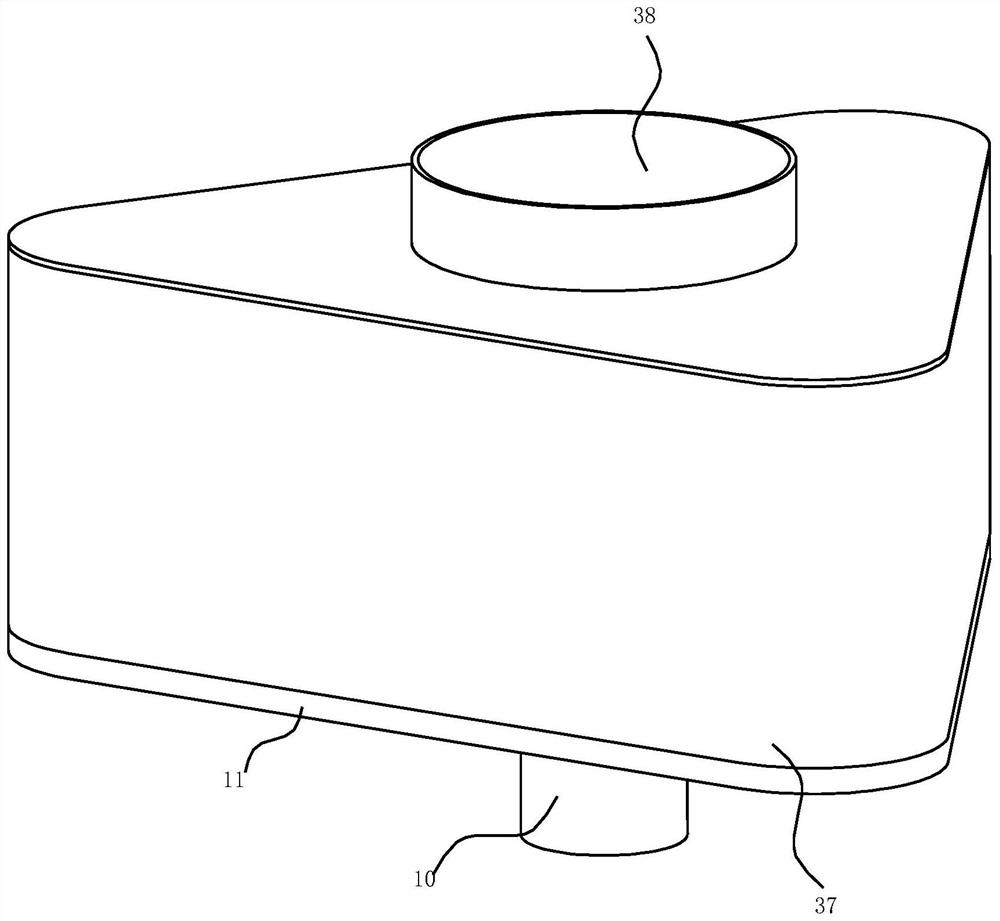
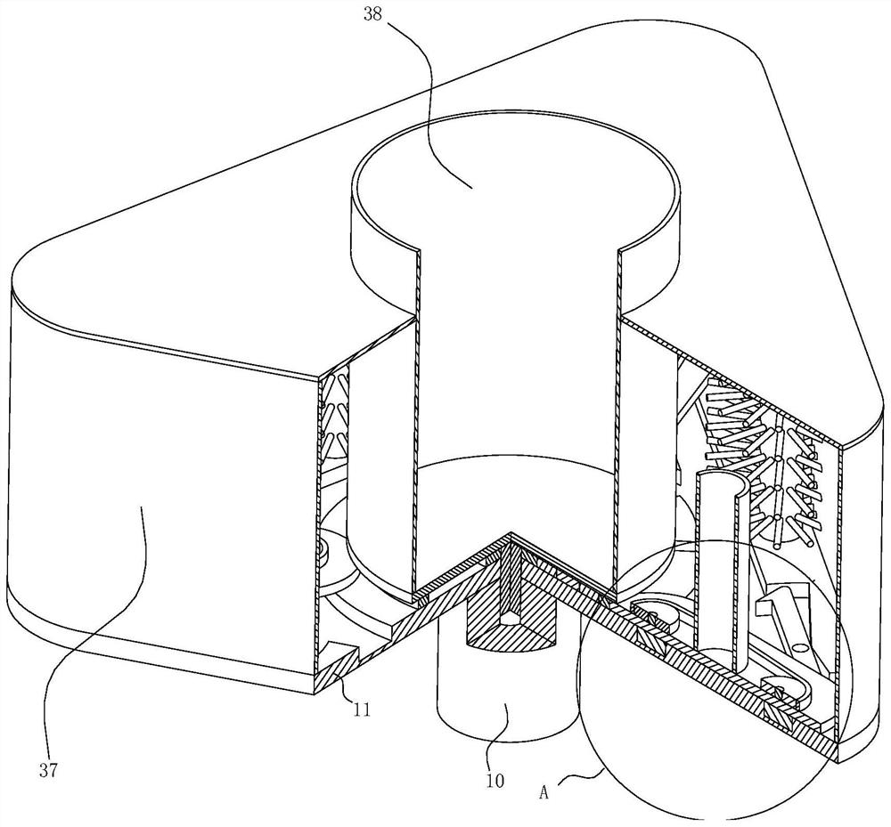
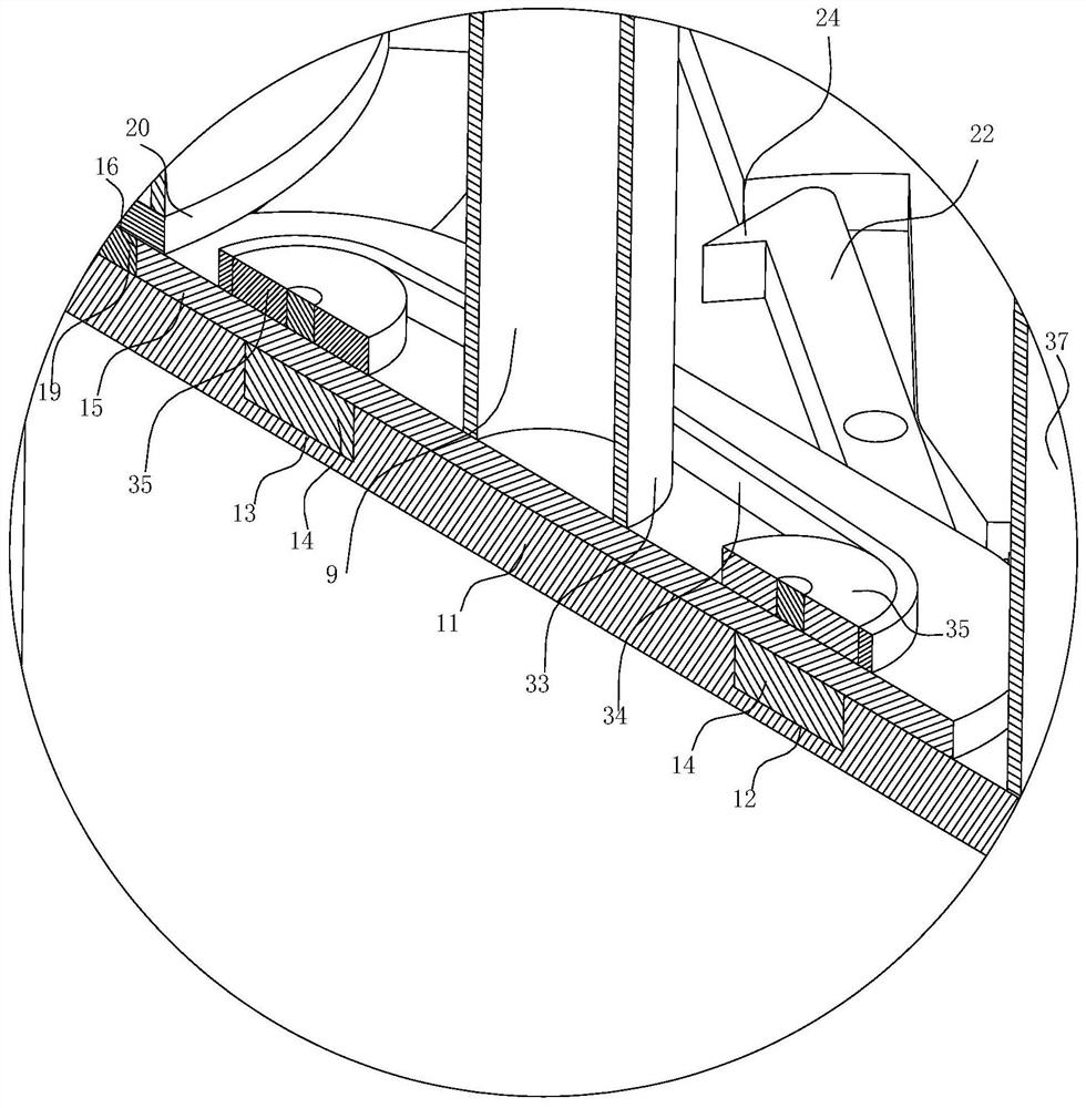
[0027] see Figure 1-7 , the present invention provides a technical solution: a sterilizing device that always maintains the best ultraviolet output, including an ultraviolet lamp 9 and a motor 10, including a triangular bottom plate 11, and a triangular chute 12 and a circular chute 13 are opened on the bottom plate 11, The two side walls of the ring chute 13 are correspondingly inscribed on the two inner walls of the triangular chute 12, and a plurality of slidin...


PUM


Abstract

The invention discloses a sterilization device capable of always keeping optimal ultraviolet output in the technical field of ultraviolet sterilization, which comprises an ultraviolet lamp and a motor and comprises a triangular bottom plate, a triangular sliding groove and an annular sliding groove are formed in the bottom plate, and the two side walls of the annular sliding groove are correspondingly internally tangent to the two inner walls of the triangular sliding groove respectively; a plurality of sliding columns are arranged in the triangular sliding groove and the annular sliding groove in a sliding mode, a mounting plate is fixedly arranged at the upper ends of every two adjacent sliding columns, and displacement teeth are arranged on the side walls of the mounting plates; the sterilization device solves the problems that an existing sterilization lamp can rotate around a to-be-sterilized object, although efficient sterilization can be conducted, stains are likely to appear on the side, facing the object, of the sterilization lamp after long-time use, and therefore the sterilization efficiency is low, and meanwhile due to the fact that the shape of the object is uncertain, and fixed-distance surrounding sterilization is conducted, sterilization dead angles are easy to appear, so that the sterilization quality is poor.

Description

technical field [0001] The invention relates to the technical field of ultraviolet ray sterilization, in particular to a sterilizing device that always maintains the best output of ultraviolet rays. Background technique [0002] Ultraviolet sterilization is the most destructive ultraviolet wavelength in the range of 240~280nm, which destroys the molecular structure of DNA (deoxyribonucleic acid) or RNA (ribonucleic acid) in bacteria and viruses, causing growth cell death and / or regenerative cell death, reaching The effect of sterilization and disinfection. Especially when the wavelength is 253.7, the bactericidal effect of ultraviolet rays is the strongest; this band coincides with the ultraviolet absorption and photochemical sensitivity range of deoxyribonucleic acid in the microbial cell nucleus. Peak at 260nm. It is generally believed that ultraviolet rays can change and destroy structural mutations, change the genetic transcription characteristics of cells, and cause o...

Claims


Application Information

Patent Timeline
Patent Type & Authority Applications(China)
IPC IPC(8): A61L2/10A61L2/26B08B1/02
CPCA61L2/10A61L2/26B08B1/02B08B1/002
Inventor 钟贵平陈丹华孔德宏
Owner 珠海天达生物科技有限公司
Why Eureka
Try Eureka