
Positioning tool based on mechanical part machining

A technology of mechanical parts and positioning tooling, which is applied in the field of mechanical parts, can solve problems such as rotation and sliding of circular mechanical parts, different sizes of mechanical parts, and positioning devices that cannot be adjusted, so as to increase friction and fixity, The effect of increasing the contact area

Inactive Publication Date: 2022-02-25
华永红
View PDF0 Cites 2 Cited by
  • Summary
  • Abstract
  • Description
  • Claims
  • Application Information

AI Technical Summary

Problems solved by technology

[0005] In order to make up for the deficiencies of the existing technology and solve the problem in the current prior art that the position of the mechanical parts is fixed first when the mechanical parts are processed, the size of the mechanical parts is different, and the traditional circular mechanical parts positioning device cannot be adjusted, resulting in Circular mechanical parts will rotate and slide, and the positioning tooling for machining of mechanical parts proposed by the present invention

Method used


Image

  • Positioning tool based on mechanical part machining
  • Positioning tool based on mechanical part machining
  • Positioning tool based on mechanical part machining

Examples


Embodiment 1

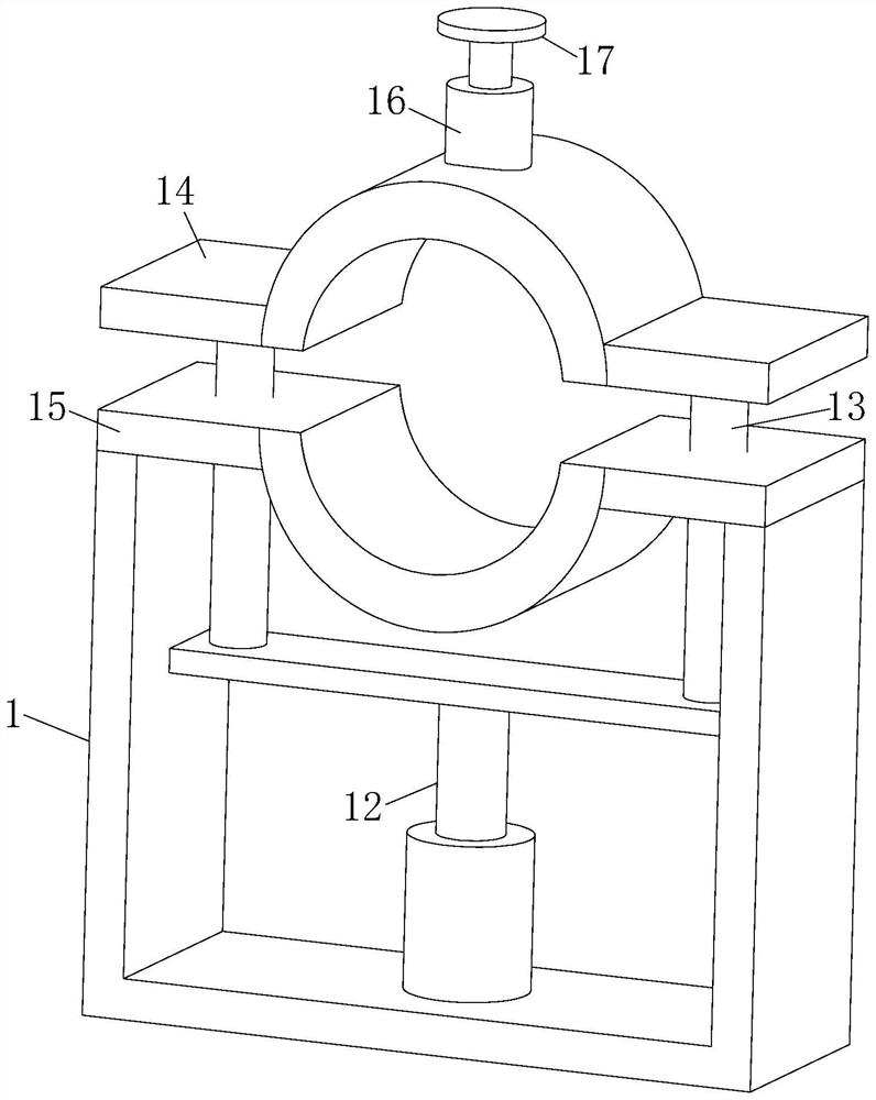
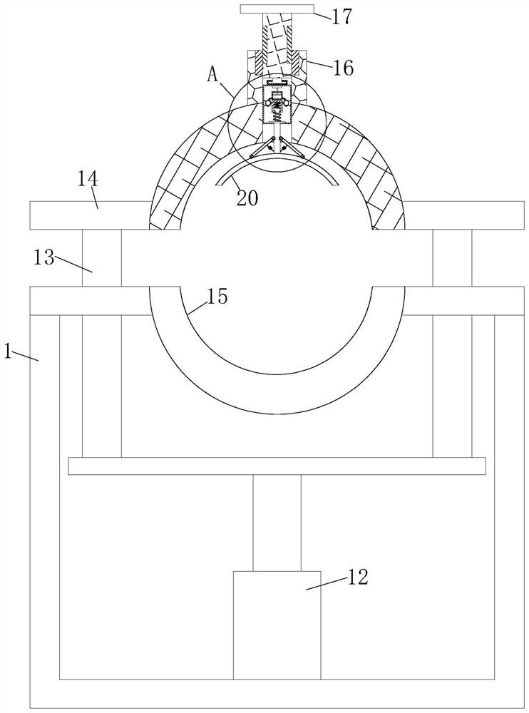
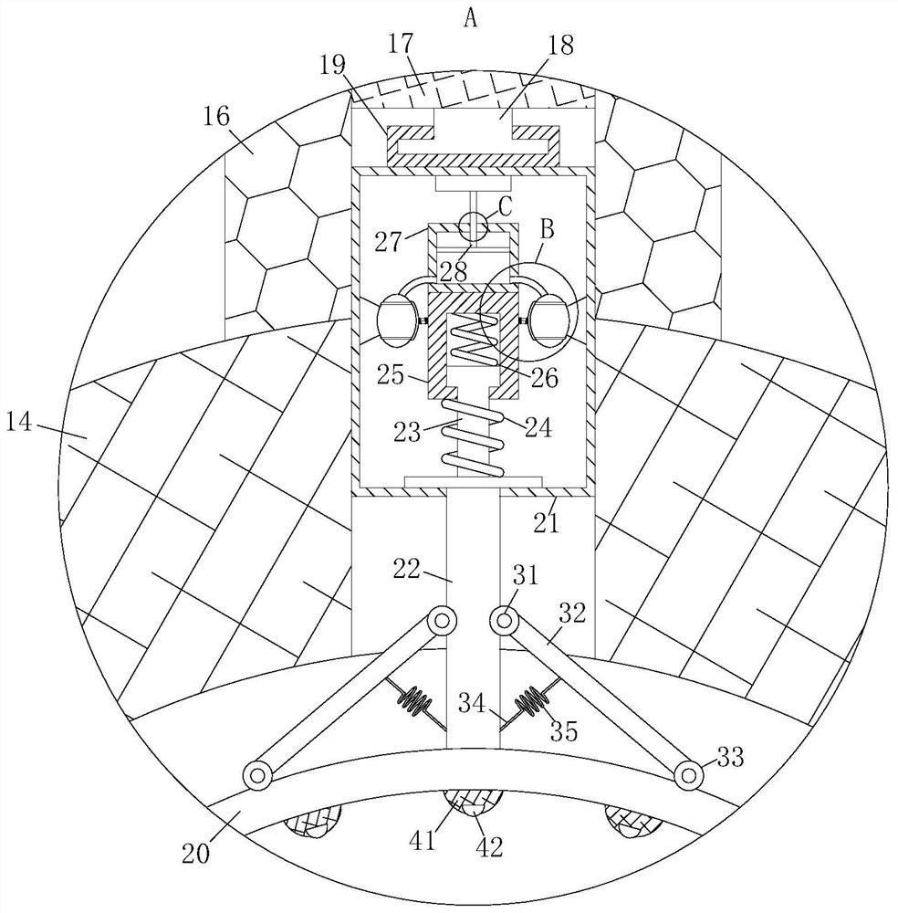
[0028] see Figure 1-5 As shown, based on the positioning tool for processing mechanical parts, it includes a board body 1; an electric push rod 12 is fixedly connected to the board body 1; a slide bar 13 is fixedly connected to the top end of the electric push rod 12; the slide bar No. 1 splint 14 is affixed to the top of 13; No. 2 splint 15 is affixed to the top of the plate body 1; Retention sleeve 16 is affixed to the middle of the No. 1 plywood 14; Rotation connection on the retention sleeve 16 There is an adjusting rod 17; the bottom end of the adjusting rod 17 is fixedly connected with a rotating rod 18; the rotating rod 18 is provided with a retaining shell 19; the bottom end of the retaining shell 19 is fixedly connected with a housing 21; The housing 21 is slidably connected with a push rod 22; the bottom end of the push rod 22 is affixed with a fixed pressure plate 20; the top end of the push rod 22 is affixed with an extruding rod 23; the extruding rod No. 1 elast...

Embodiment 2

[0037] see Figure 6 As shown in Comparative Example 1, as another embodiment of the present invention, the oil scraper 46 is affixed to the top of the oil absorbing plate 40; during operation, the oil in the oil tank 38 is coated on the side of the pusher plate 28 At the wall, the oil will slide with the sliding of the pusher plate 28, and the inside of the oil scraper 46 is provided with a scraper, and the oil on the pusher plate 28 can be scraped off by the oil scraper 46, so as to avoid a large amount of oil The air plate 28 slides, causing oil to leak at the side wall between the air cylinder member 27 and the pusher plate 28 .

[0038] Working principle: When working, place the circular mechanical parts to be processed on the No. 2 splint 15, start the electric push rod 12 to make the slider 13 slide down, and the sliding of the slider 13 will make the No. 1 splint 14 slide down first. , cooperate with No. 2 splint 15 to fix the circular mechanical parts. If the volume ...


PUM


Abstract

The invention belongs to the technical field of mechanical parts, and particularly relates to a positioning tool based on mechanical part machining. The positioning tool comprises a plate body; the plate body is fixedly connected with an electric push rod; the top end of the electric push rod is fixedly connected with a sliding rod; a first clamping plate is fixedly connected to the top end of the sliding rod; a second clamping plate is fixedly connected to the top end of the plate body; a retention sleeve is fixedly connected to the middle of the first clamping plate; an adjusting rod is rotationally connected to the retention sleeve; the bottom end of the adjusting rod is fixedly connected with a rotating rod; and a retention shell is arranged on the rotating rod. A fixing pressing plate can be adjusted through rotation of the adjusting rod, the fixity of the fixing pressing plate to a mechanical part can be improved through cooperation of a first elastic piece and a second elastic piece, the contact area between the fixing pressing plate and the circular mechanical part can be increased, and therefore, friction force and fixity are increased; and the conditions of rotation and sliding in the machining process are avoided.

Description

technical field [0001] The invention belongs to the technical field of mechanical parts, and in particular is based on a positioning tool for processing mechanical parts. Background technique [0002] Mechanical parts, also known as mechanical components, are the basic components of machinery. In the production process of mechanical parts, multiple processing procedures are required. They are inseparable individual parts that make up machinery and machines. [0003] The connection of parts includes screw connection, wedge connection, pin connection, key connection, spline connection, interference fit connection, elastic ring connection, riveting, welding and gluing, etc. [0004] In the current existing technology, the position is fixed first when the mechanical parts are processed. The size of the mechanical parts is different. The traditional circular mechanical part positioning device cannot be adjusted, resulting in rotation and sliding of the circular mechanical parts d...

Claims


Application Information

Patent Timeline
IPC IPC(8): B25B11/00
CPCB25B11/00
Inventor 华永红
Owner 华永红
Learn More