Sensor heat insulation structure

A technology of sensor and heat shield, applied in the field of sensor heat insulation structure

Active Publication Date: 2022-02-25
SHANGHAI MICRO ELECTRONICS EQUIP (GRP) CO LTD
View PDF10 Cites 0 Cited by
  • Summary
  • Abstract
  • Description
  • Claims
  • Application Information

AI Technical Summary

Problems solved by technology

[0004] The purpose of the present invention is to provide a sensor heat insulation structure to solve one or more problems existing in the existing sensor heat insulation structure

Method used


Image

  • Sensor heat insulation structure
  • Sensor heat insulation structure
  • Sensor heat insulation structure

Examples


Embodiment Construction

[0023] The heat insulation structure of the sensor proposed by the present invention will be further described in detail below in conjunction with the accompanying drawings and specific embodiments. The advantages and features of the present invention will become clearer from the following description. It should be noted that all the drawings are in a very simplified form and use imprecise scales, and are only used to facilitate and clearly assist the purpose of illustrating the embodiments of the present invention. In addition, the structures shown in the drawings are often a part of the actual structure. In particular, each drawing needs to display different emphases, and sometimes uses different scales.

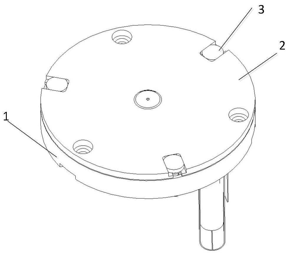
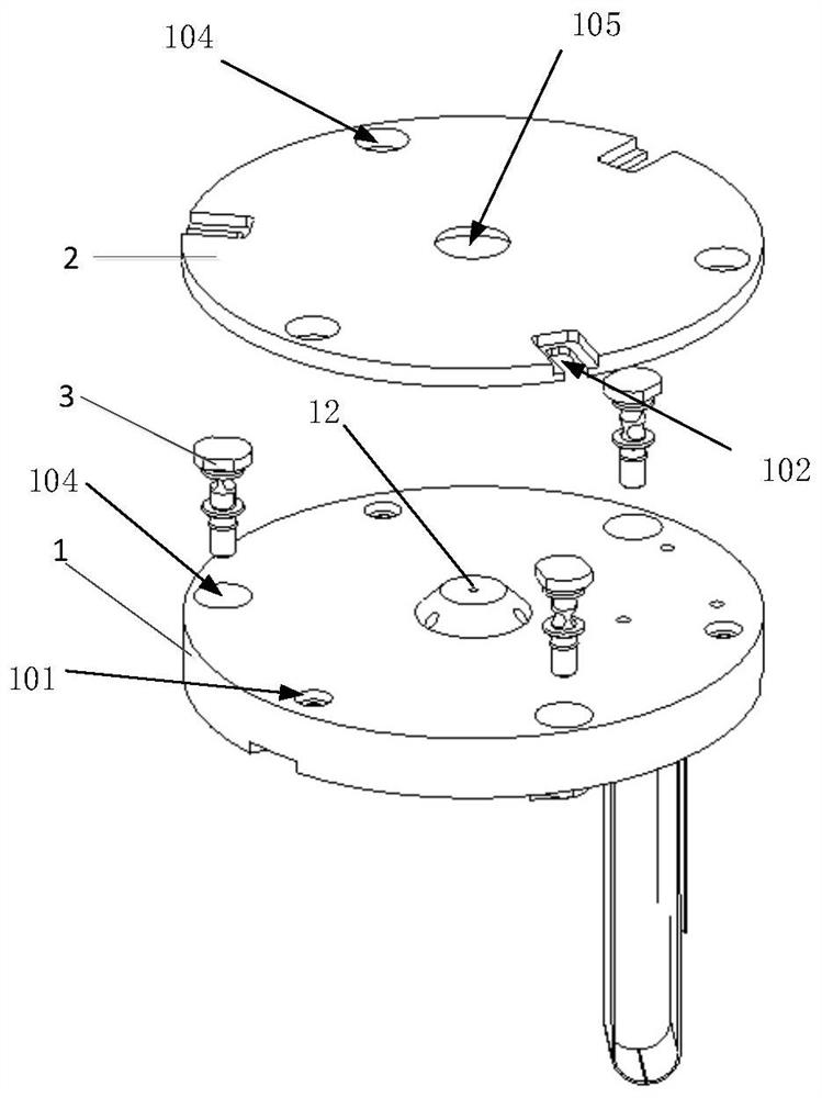
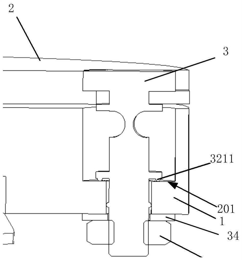
[0024] Please refer to figure 1 , figure 2 and image 3 and combine Figure 4 , the present embodiment provides a sensor heat insulation structure, including: a base 1, a heat shield 2 and a connecting support 3, the base 1 has an opposite top surface and a bottom su...


PUM


Abstract

A sensor heat insulation structure provided by the present invention comprises a base, heat insulation plates and a connection support, the base has a top surface and a bottom surface opposite to each other, the heat insulation plates are arranged on the top surface of the base at intervals through the connection support, the connection support comprises a first part and a second part which are sequentially connected along the axial direction, the first part is used for penetrating through the base, and the second part is used for clamping the heat insulation plates to limit the positions of the heat insulation plates. Compared with the prior art, due to the fact that the heat insulation plates and the base are arranged in the spaced mode through the connection support, the mode that glue is dispensed through a rubber spacer is not needed any more, and the situation that glue loses efficacy due to high and low temperature circulation impact is avoided; besides, one part of the connection support is connected with the heat insulation plates in a clamping mode to limit the positions of the heat insulation plates, the other part of the connection support penetrates through the base to fix the position of the connecting support, and compared with a dispensing fixing mode, the assembling precision is higher, and the assembling is easier and more convenient.

Description

technical field [0001] The invention relates to the technical field of photolithography equipment, in particular to a sensor heat insulation structure. Background technique [0002] The heat insulation structure of the sensor on the existing lithography machine adopts the method of rubber spacer dispensing to install the heat shield on the base. The function of the heat shield is to absorb a large amount of heat brought by the spot, and distribute the rubber spacer It is to prevent the heat absorbed by the heat shield from being transferred to the base. [0003] In actual use, there is a working condition where the sensor receives a large amount of heat intermittently, that is, there is a working condition of impact thermal load, so there is a high and low temperature cycle at the spacer ring dispensing, resulting in the structure's impact on the glue. The characteristic requirements are high, and the glue is prone to failure after being heated. In addition, due to the exi...

Claims


Application Information

Patent Timeline
Patent Type & Authority Applications(China)
IPC IPC(8): F16L59/02F16L59/12F16B35/04G01D11/00
CPCF16L59/021F16L59/028F16L59/12F16B35/041G01D11/00
Inventor 尹光才马汝坤彭云平
Owner SHANGHAI MICRO ELECTRONICS EQUIP (GRP) CO LTD
Why Eureka
Try Eureka