Backlight module and display device

A backlight module and display panel technology, which is applied in the directions of identification devices, optics, nonlinear optics, etc., can solve problems such as poor display effect, loose optical film layer, warping deformation, etc., to avoid warping and deformation of the diaphragm, and solve Shadows, effects that enhance the display

Pending Publication Date: 2022-02-25
CHANGSHA HKC OPTOELECTRONICS CO LTD +1
View PDF0 Cites 2 Cited by
  • Summary
  • Abstract
  • Description
  • Claims
  • Application Information

AI Technical Summary

Problems solved by technology

[0003] The purpose of the present application is to provide a backlight module and a display device, aiming to solve the problem of poor display effect due to easy loosening and warping of the optical film layer in the backlight module

Method used


Image

  • Backlight module and display device
  • Backlight module and display device
  • Backlight module and display device

Examples


Embodiment 1

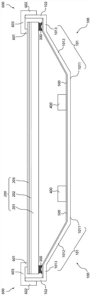
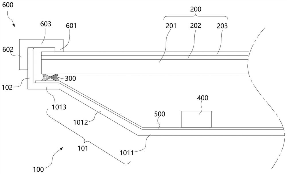
[0039] The embodiment of the present application discloses a backlight module, such as figure 1 As shown, it includes a backplane 100 , an optical film layer 200 , an elastic buffer 300 , a light source 400 , a reflection sheet 500 and a limiting frame 600 . Wherein, the elastic buffers 300 on both sides are arranged between the edge of the optical film layer 200 and the back plate 100, the optical film layer 200 can be supported by the elastic buffers 300; and, since the elastic buffers 300 on both sides have The elastic buffer force, therefore, plays a certain buffering role on the optical film layer 200, avoiding problems such as damage to the diffuser plate; wherein, when the optical film layer 200 is placed horizontally, the elastic buffer member 300 exerts an upward elastic force on the optical film layer 200 Support force, and cooperate with the limit frame 600, clamp the optical film layer 200 between the elastic buffer 300 and the limit frame 600, avoid the optical fi...

Embodiment 2

[0071] The difference between Embodiment 2 and Embodiment 1 is that, as image 3 and Figure 4 As shown, the elastic buffer 300 also includes an upper adsorption groove 3014, and the upper adsorption groove 3014 is arranged on the upper part of the elastic buffer 300, wherein the upper adsorption groove 3014 is arranged on the opposite side of the lower adsorption groove 3015, and The lower adsorption groove 3015 is connected to the side away from the fixing plate 1013 , the opening of the upper adsorption groove 3014 faces the side of the diffuser plate 201 , and the end faces of the two ends of the opening are abutted and connected with the diffuser plate 201 .

[0072] It should be noted that, if Figure 4 As shown, the specific structure of the upper adsorption groove 3014 and the lower adsorption groove 3015 is the same, and the vacuum adsorption principle is the same as that of the lower adsorption groove 3015 and the fixed plate 1013, so it will not be repeated here; i...

Embodiment 3

[0075] The difference between embodiment three and embodiment two is that, as Figure 5 and Image 6 As shown, the elastic buffer 300 also includes an elastic extension part 302, and the elastic extension part 302 is respectively connected with the film layer of the lower adsorption groove 3015 near the side plate 102 and the upper adsorption groove 3014 near the side plate 102. The film layer is connected, and forms a through hole 3013 with the lower adsorption groove 3015 and the upper adsorption groove 3014, so as to better provide elastic deformation capability; in addition, the elastic extension part 302 is along the vertical direction from the fixed plate 1013 to the diffuser plate 201 direction, and abut against the diffusion plate 201, the diffusion film 203, and the enhancement film 202 on the side close to the side plate 102, so as to abut against the edges of the diffusion plate 201, the enhancement film 202, and the diffusion film 203. The elastic buffer 300 is pr...


PUM


Abstract

The invention belongs to the technical field of display, and particularly relates to a backlight module and a display device, and the backlight module comprises: a back plate which comprises a bottom plate; an optical film layer, wherein the edge of the optical film layer is supported on the bottom plate; a limiting frame, wherein the limiting frame comprises a first limiting part, and the first limiting part is located on the side, away from the bottom plate, of the optical film layer and abuts against the edge of the optical film layer; and an elastic buffer piece, wherein at least part of the elastic buffer piece is arranged between the edge of the optical film layer and the bottom plate, and / or is arranged between the edge of the optical film layer and the first limiting part. The display device comprises a display panel and a backlight module. The display panel is arranged on the light emitting side of the backlight module; an elastic supporting force is provided for the diffusion plate through the elastic buffer piece, so that the optical film layer is clamped between the elastic buffer piece and the limiting frame, the problems of wrinkling and loosening of a diaphragm of the optical film layer due to the influence of gravity are solved, and the display effect is further improved.

Description

technical field [0001] The present application belongs to the field of display technology, and in particular relates to a backlight module and a display device. Background technique [0002] Currently, commonly used backlight modules include side-type backlight modules and direct-type backlight modules. The direct-type backlight module is usually equipped with an optical film layer to homogenize the light, but the optical film layer and the diffuser plate are easily affected by their own gravity, resulting in loosening of the edge fixing, which is easy to cause the optical film layer and the diffuser plate to be loose. The problems of looseness and warping between the layers itself make the optical characteristics of the backlight module worse, which in turn makes the display effect worse. Contents of the invention [0003] The purpose of the present application is to provide a backlight module and a display device, aiming at solving the problem that the optical film laye...

Claims


Application Information

Patent Timeline
Patent Type & Authority Applications(China)
IPC IPC(8): G02F1/1333G02F1/1335G02F1/13357G09F9/33
CPCG02F1/133308G02F1/133608G02F1/133512G02F1/133606G09F9/33
Inventor 龚荣袁海江
Owner CHANGSHA HKC OPTOELECTRONICS CO LTD
Why Eureka
Try Eureka