Power supply line connecting device of electric locomotive

A technology of connecting device and electric locomotive, applied in the direction of connection, circuit, collector, etc., can solve the problems of failure, potential safety hazard, affecting the power supply and operation of the mine, etc., to extend the service life, ensure safety, reduce collision effect

Pending Publication Date: 2022-02-25
SHANDONG ZHAOJIN GOLD & SILVER REFINERY
View PDF0 Cites 0 Cited by
  • Summary
  • Abstract
  • Description
  • Claims
  • Application Information

AI Technical Summary

Problems solved by technology

[0003] When the electric locomotive is running, the pantograph of the electric locomotive will smoothly pass through the neutral position and enter the next section of wire by using the inertia. T

Method used


Image

  • Power supply line connecting device of electric locomotive
  • Power supply line connecting device of electric locomotive
  • Power supply line connecting device of electric locomotive

Examples


Embodiment 1

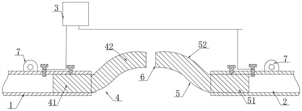
[0024] Example 1, such as figure 1 As shown, a power supply line connecting device of an electric locomotive comprises adjacent first galvanized pipe 1, second galvanized pipe 2 and section switch 3, and a terminal of said section switch 3 is connected to the first galvanized pipe The galvanized pipe 1 is connected, and the other terminal is connected with the second galvanized pipe 2, and also includes a first insulating rod 4 connected with the first galvanized pipe 1 and a second insulating rod connected with the second galvanized pipe 2 5. There is a gap 6 between the first insulating rod 4 and the second insulating rod 5 .

[0025] The first insulating rod 4 includes a first connecting portion 41 and a first bending portion 42, the first connecting portion 41 is inserted into the first galvanized pipe 1 and locked by bolts, and the first bending portion The bending direction of 42 is upward. The connecting part of the insulating rod is inserted and matched with the galv...

Embodiment 2

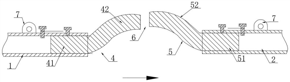
[0029] Example 2, such as figure 2 As shown, on the basis of Embodiment 1, the electric locomotive drives from the first galvanized pipe 1 to the second galvanized pipe 2, and the centerline of the second curved portion 52 is higher than the first curved Centerline of section 42. Although the reduction of the gap 6 and the design of the bending part can satisfy the smooth passage of the pantograph through the neutral position, in order to further reduce the wear of the end of the bending part by the pantograph at the position of the gap 6, the bending part that is heading towards The setting position is higher, further reducing the contact between the pantograph and the end of the bending part, and further improving the transition effect of the pantograph in neutral.

Embodiment 3

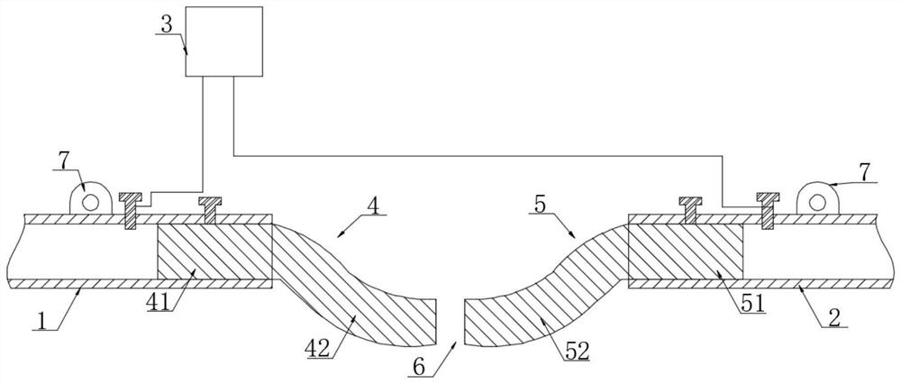
[0030] Example 3, such as image 3 As shown, the first insulating rod 4 includes a first connecting portion 41 and a first bending portion 42. The first connecting portion 41 is inserted into the first galvanized pipe 1 and locked by bolts. A bending direction of the bending portion 42 is downward. The connecting part of the insulating rod is plugged and matched with the galvanized pipe. There are bolt holes on the galvanized pipe. The rod of the bolt passes through the bolt hole and acts on the connecting part to realize the connection between the insulating rod and the galvanized pipe. The downward bending part is matched. Forming a concave design can also cooperate with the elastic force of the pantograph to ensure that the pantograph passes through the gap 6 smoothly.

[0031] The second insulating rod 5 includes a second connecting portion 51 and a second bending portion 52, the second connecting portion 51 is inserted into the second galvanized pipe 2 and locked by bolt...


PUM


Abstract

The invention discloses a power supply line connecting device of an electric locomotive. The device comprises a first galvanized pipe, a second galvanized pipe and a section switch which are adjacent to each other; one wiring end of the section switch is connected with the first galvanized pipe, and the other wiring end of the section switch is connected with the second galvanized pipe. The device further comprises a first insulating rod connected with the first galvanized pipe, and a second insulating rod connected with the second galvanized pipe, and a gap is formed between the first insulating rod and the second insulating rod. According to the device of the invention, the distance of a neutral position is shortened; on the basis of the elastic force of a pantograph, it can be ensured that the pantograph smoothly passes through the neutral position between the the adjacent galvanized pipes, the collision of the pantograph to the pipe ends of the galvanized pipes is reduced; and in a humid environment under a mine, if the adjacent insulating rods are connected, the danger of electric conduction still exists under the condition that the section switch is switched off, and however, the gap reserved between the insulating rods avoids the situation, so that the wire of the electric locomotive is safer and more reliable, the service life of the wire of the electric locomotive is prolonged, and the safety of an operator in the mine during maintenance is ensured.

Description

technical field [0001] The invention relates to a power supply line connecting device of an electric locomotive, and belongs to the technical field of mine car power supply. Background technique [0002] In the tunnel under the mine, the electric locomotive is connected to the power supply line on the top of the tunnel through a pantograph. In order to facilitate the control and maintenance of the tunnel under the mine, the power supply line on the top of the tunnel is generally about 500 meters and a section switch will be set. A 200-300mm gap is required on the line between the two connection ends of the section switch. [0003] During the operation of the electric locomotive, the pantograph of the electric locomotive will smoothly pass through the neutral position and enter the next section of wire by using the inertia. The end of the long-term and multiple collisions will often cause failures in the line, which will not only affect the power supply and operation under t...

Claims


Application Information

Patent Timeline
IPC IPC(8): H01R41/00
CPCH01R41/00
Inventor 王建军李尚远冯桂坤王兵强
Owner SHANDONG ZHAOJIN GOLD & SILVER REFINERY
Why Eureka
Try Eureka