Wireless device

A wireless device and antenna technology, applied in the field of wireless devices, can solve problems such as reducing energy efficiency on the network side, and achieve the effect of reducing total power consumption

Pending Publication Date: 2022-02-25
TELEFON AB LM ERICSSON (PUBL)
View PDF0 Cites 0 Cited by
  • Summary
  • Abstract
  • Description
  • Claims
  • Application Information

AI Technical Summary

Problems solved by technology

[0004] An alternative proposed in 3GPP document R1-1812363 is to broadcast from the network an additional reference signal that the UE can use to tune its AGC, but this reduces the energy efficiency on the network side

Method used


Image

  • Wireless device
  • Wireless device
  • Wireless device

Examples


Embodiment Construction

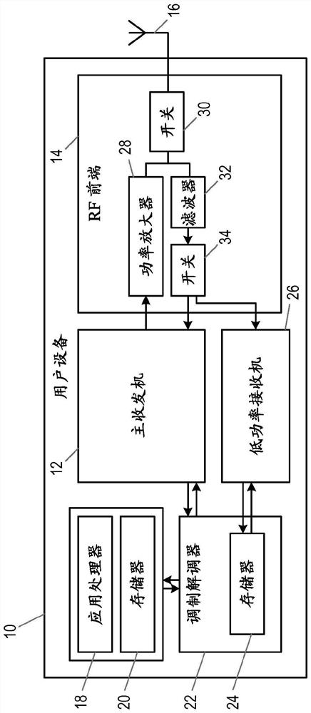
[0023] figure 1 A wireless device according to the present disclosure is shown. In this example, the wireless device takes the form of a user equipment (UE) 10 configured for use in a cellular communication network. However, a wireless device may take the form of any device designed to receive wireless signals.

[0024] The UE includes a radio frequency (RF) transceiver 12 configured to transmit and receive cellular signals via RF front-end circuitry 14 and antenna 16 . This allows the UE to communicate with a radio access node of the cellular network, such as a base station (gNB), in a generally conventional manner.

[0025] The UE 10 also includes an applications processor 18 and its associated memory 20 configured to run the UE's operating system and application software. Additionally, UE 10 includes a baseband processor or modem 22 and its associated memory 26 for cellular communications.

[0026] In this embodiment, the UE 10 also includes an additional or auxiliary r...


PUM


Abstract

A wireless device comprises at least one antenna and a main receiver, having first automatic gain control circuitry for controlling a gain applied to signals received by means of the antenna. The wireless device further comprises an auxiliary receiver, configured to monitor a power of a periodic reference signal received by means of the antenna, and further configured to send power information to the main receiver. The main receiver is configured, on waking up, to use the power information received from the auxiliary receiver to assist in operation of the first automatic gain control circuitry.

Description

technical field [0001] The present invention relates to wireless devices and, in particular, to receiver circuitry in wireless devices. Background technique [0002] In wireless receivers, automatic gain control (AGC) is often used to ensure that the amplitude of the received signal is adapted so that the signal processing functions in the receiver operate optimally. [0003] In the case of a user equipment (UE) in a cellular communication network, the UE spends a portion of its time in a sleep state in order to prolong its battery life, periodically waking up from the sleep state to receive and decode paging information. The UE has to perform AGC based on the reference signals it receives from the network in order to be able to receive and decode paging messages. However, this may require the receiver to wake up from the sleep state to receive the reference signal and perform AGC, and then the receiver cannot return to the sleep state until it receives the paging message. ...

Claims


Application Information

Patent Timeline
IPC IPC(8): H04W52/02H04W88/06H04W68/00H04W56/00
CPCH04W52/0274H04W56/001H04W52/0229H04W52/0245Y02D30/70H04W52/52
Inventor G·邹H·斯约兰德
Owner TELEFON AB LM ERICSSON (PUBL)
Why Eureka
Try Eureka