Multi-frequency low-power-consumption oscillator and control method
A technology of oscillator and oscillation module, which is applied in the field of communication, can solve problems such as high power consumption, and achieve the effects of reducing errors, reducing overall power consumption, and reducing power consumption of the overall clock system
- Summary
- Abstract
- Description
- Claims
- Application Information
AI Technical Summary
Problems solved by technology
Method used
Image
Examples
Embodiment 1
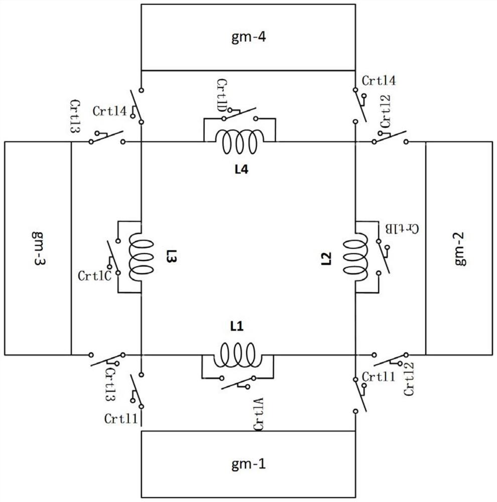
[0048] An embodiment of the present invention provides an oscillator, which may include:
[0049] The first oscillation module includes a control switch, a negative resistance generation module and an inductance module, the negative resistance generation module and the inductance module form a resonant circuit, and the control switch is used to select the bypassed mode or the inductance of the resonant circuit select mode;
[0050] The second oscillating module includes an oscillating module that is the same as or equivalent to the first oscillating module, wherein the same or equivalent is relative to the constituent elements and the way of construction, such as a plurality of inductance modules connected in series and parallel can be equivalent to an inductance module;
[0051] At least one of the resonant circuits in the first oscillating module and the resonant circuit in the second oscillating module is in the selected mode;
[0052] The resonant circuit in the first os...
Embodiment 2
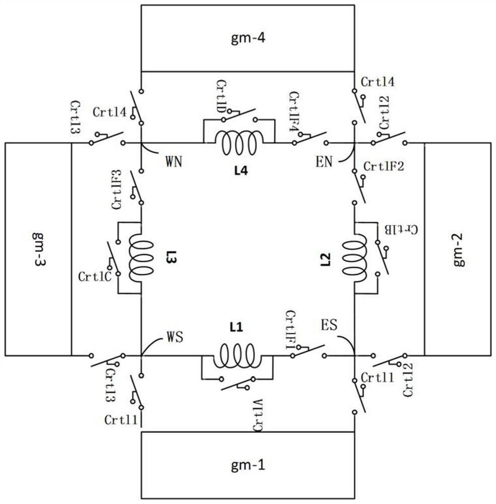
[0073] Based on Embodiment 1, the embodiment of the present invention provides an oscillator of the array, and the oscillation modules in the oscillator are the same modules, including:
[0074] P oscillation modules, where P is a positive integer greater than or equal to 4;
[0075] Each oscillation module includes a negative resistance generation module, an inductance module and a control switch;
[0076] The negative resistance generating module and the inductance module form a resonant circuit;
[0077] The control switch is connected in parallel with the inductance module, and is used to select the bypassed mode or the selected mode of the resonant tank;
[0078] The inductance modules in the P oscillation modules are connected in series to form an output loop;
[0079] The clock signal output by the output circuit is superimposed with the clock signal output by the resonant circuit in the selected mode.
[0080] In some specific implementations, the clock signals outp...
Embodiment 3
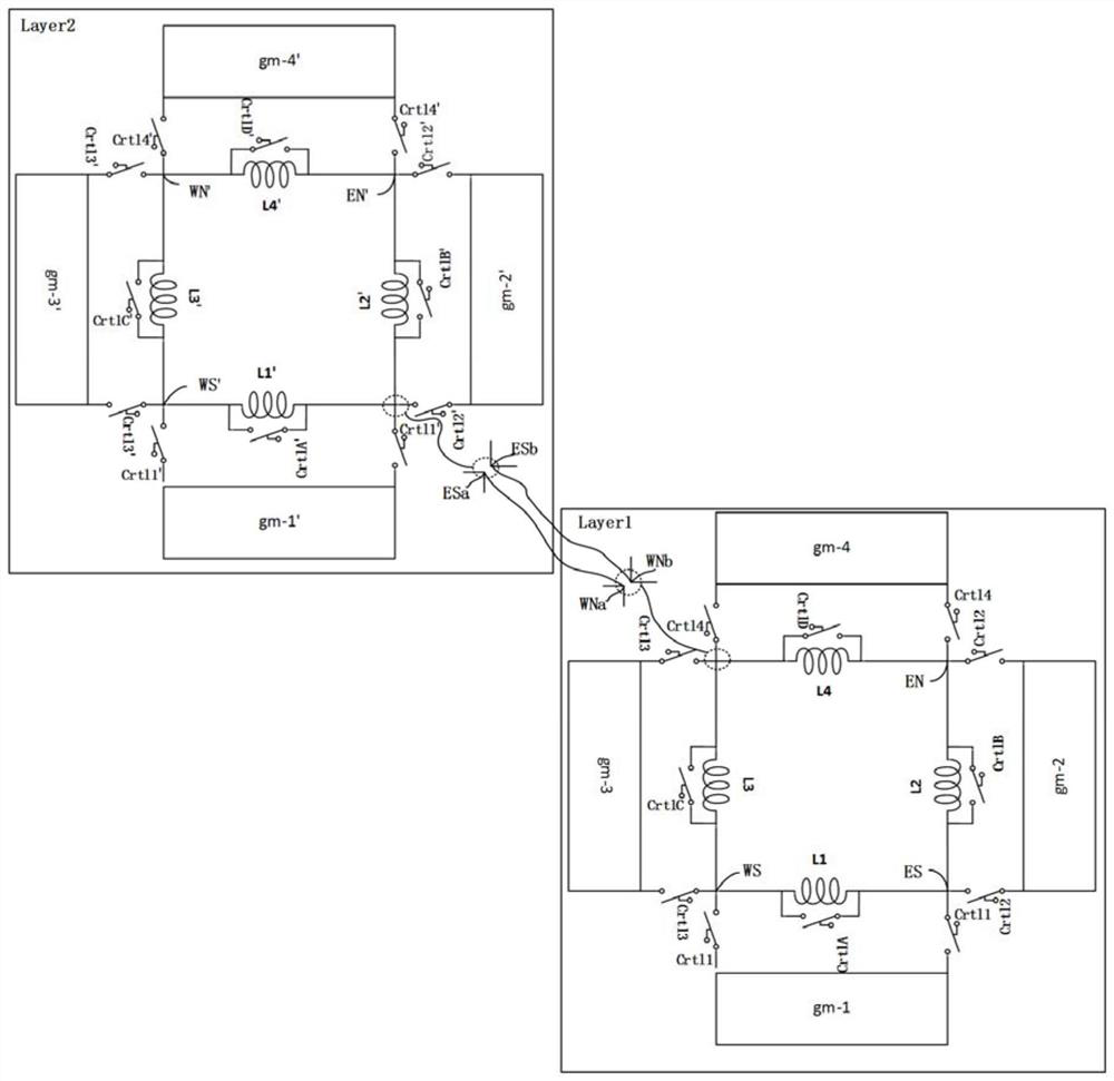
[0090] Based on Embodiment 2, the embodiment of the present invention provides a stacked oscillator, which includes:
[0091] The P oscillation modules described in Embodiment 2;
[0092] The P oscillating modules are arranged in Q layout layers, wherein Q is a positive integer greater than or equal to 2, and each layout layer has at least one oscillating module.
[0093] Preferably, at least one layout layer has 4 oscillating modules, and the 4 oscillating modules are symmetrically arranged.
[0094] In some specific implementations, in order to achieve more frequency combinations, after setting 4 oscillation modules on the bottom layout layer, multiple layout layers can be set on the bottom layout layer, each layout layer has 4 vibration modules, There may be insulating isolation layers and support columns between the layout layers.
[0095] In some implementations, such as image 3, Q is taken as 2, the oscillator includes two layout layers, each layout layer has 4 oscil...
PUM
 Abstract
Description
Claims
Application Information
 - R&D
- Intellectual Property
- Life Sciences
- Materials
- Tech Scout
- Unparalleled Data Quality
- Higher Quality Content
- 60% Fewer Hallucinations
Browse by: Latest US Patents, China's latest patents, Technical Efficacy Thesaurus, Application Domain, Technology Topic, Popular Technical Reports.
© 2025 PatSnap. All rights reserved.Legal|Privacy policy|Modern Slavery Act Transparency Statement|Sitemap|About US| Contact US: help@patsnap.com


