Ignition coil dwell control

An ignition coil and dwell time technology, applied in ignition controllers, spark ignition controllers, engine ignition, etc., can solve the problems of increasing the overall wear of the ignition system, increasing the size of the spark plug gap, increasing the wear of the ignition system, etc. Heat generation and aging, wear rate prolongation, effect of reducing component stress

Pending Publication Date: 2019-04-02
FORD GLOBAL TECH LLC
View PDF0 Cites 0 Cited by
  • Summary
  • Abstract
  • Description
  • Claims
  • Application Information

AI Technical Summary

Problems solved by technology

However, while high current supplied to the ignition coil produces high spark energy with long spark duration during conditions of high engine speed and load, the high current supply can also bring about premature wear of the spark plug gap through electrode combustion , thereby increasing the spark plug gap si

Method used


Image

  • Ignition coil dwell control
  • Ignition coil dwell control
  • Ignition coil dwell control

Examples


Embodiment Construction

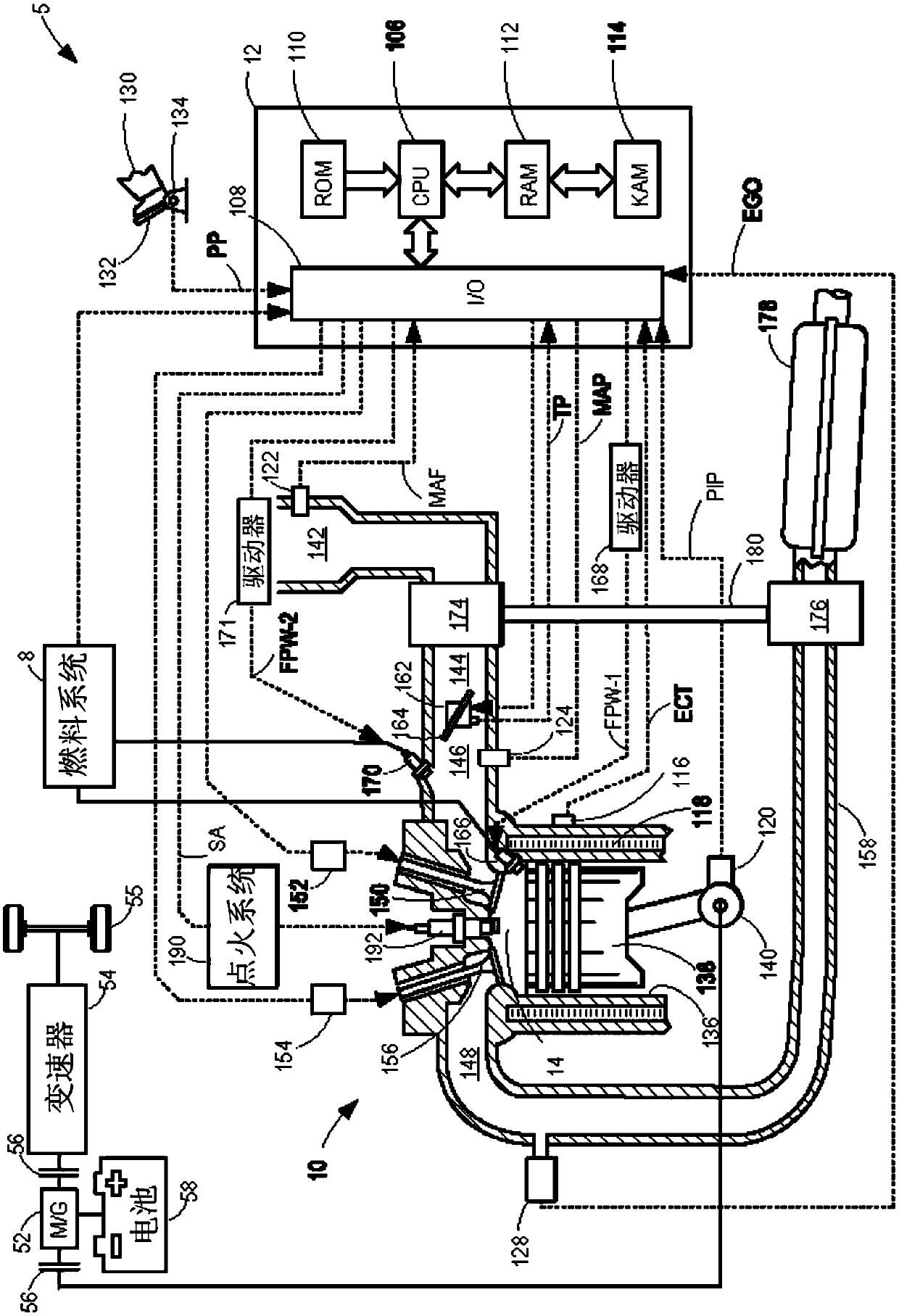
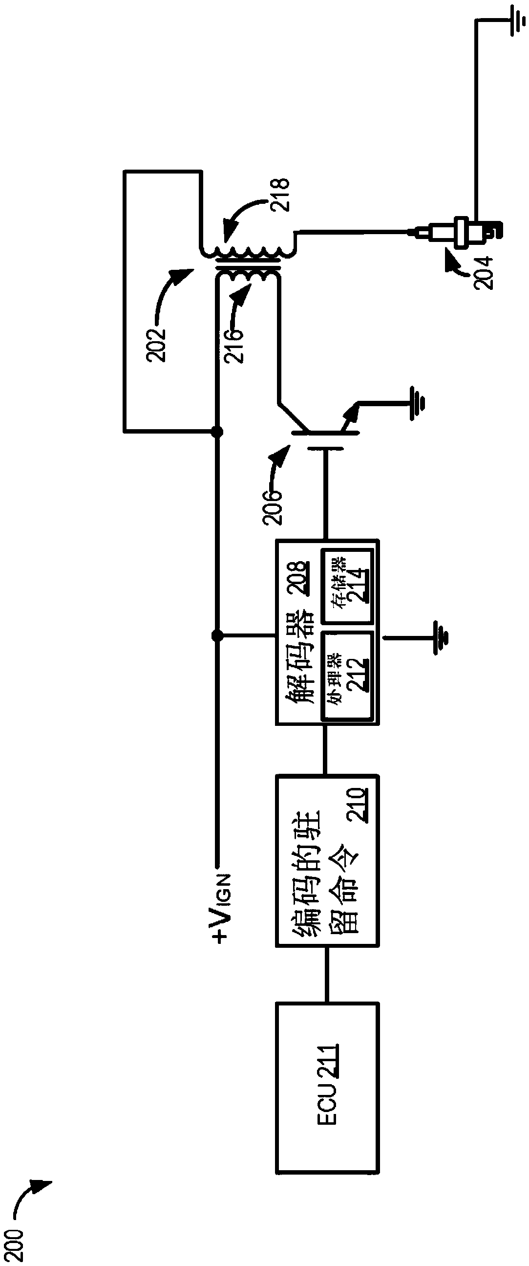
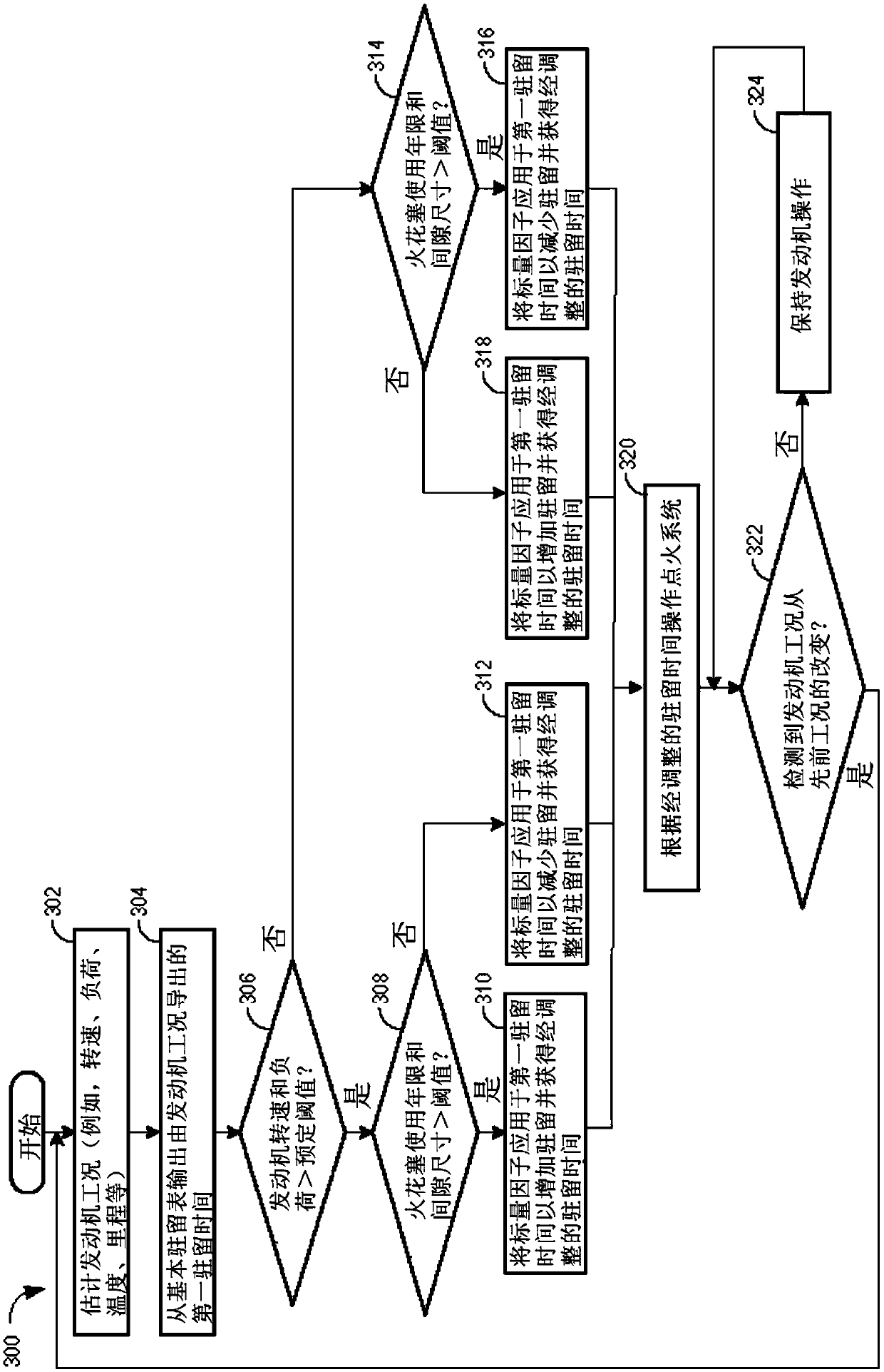
[0012] The following description relates to control of internal combustion engines such as figure 1 A system and method for dwell time in an ignition system of an example engine system. Optimum engine performance can be achieved by: when the engine is operating at high rpm and high load conditions, by figure 2 High pressure spark energy is provided in the ignition system shown) for higher dwell, while for engines operating at low rpm and low load conditions, dwell is increased to provide longer spark duration. The provided baseline dwell amount may be obtained from a base dwell look-up table included in the vehicle's control module. The baseline dwell time may additionally be calibrated to be proportional to spark plug condition (eg, age and gap size between spark plug electrodes). The spark plug gap size can be calculated based on accumulated mileage information, electrode material, and the geometry of the spark plug assembled in the ignition system. Based on the calculat...


PUM


Abstract

The invention relates to ignition coil dwell control. Approaches for controlling dwell time in the ignition system of an internal combustion engine are provided. In one example, a method may include adjusting dwell based on engine operating conditions and further adjusting dwell in a manner proportional to existent spark plug conditions. By constantly assessing spark plug condition during operating of the internal combustion engine, premature wear of the spark plug may be prevented leading to an extension in the service life of spark plug and other ignition system components.

Description

technical field [0001] The present specification generally relates to methods and systems for controlling dwell time proportional to spark plug life in an ignition system of an internal combustion engine. Background technique [0002] Engine systems with spark ignition modules may be configured to achieve peak power output to meet engine operating requirements. In an induction spark ignition engine, the ignition coil provides the necessary spark energy to cause the spark plug to ignite a homogeneous air-fuel mixture in the combustion chamber, causing the engine to spin. The ignition coil includes a primary winding and a secondary winding. One end of the primary winding is connected to the battery (eg 12V DC), with high peak current flowing steadily from the battery through the primary winding of the coil to establish an electromagnetic field in the ignition coil core, and the other end is connected to the switching mechanism. The tip of a spark plug contains a gap that vol...

Claims


Application Information

Patent Timeline
IPC IPC(8): F02P9/00
CPCF02P9/00F02P3/0456F02P5/151F02P13/00
Inventor N·W·小莫如R·汉弗莱O·贝克迈尔
Owner FORD GLOBAL TECH LLC
Why Eureka
Try Eureka