Swing mechanism of plate shearing machine

A technology of swing mechanism and shearing machine, applied in shearing machine equipment, shearing device, accessories of shearing machine, etc., can solve the problems of inconvenient integrated production, unfavorable automatic production, and inability to achieve continuous processing in a streamlined manner. The effect of being conducive to automated production

Inactive Publication Date: 2022-03-01
张建成
View PDF1 Cites 0 Cited by
  • Summary
  • Abstract
  • Description
  • Claims
  • Application Information

AI Technical Summary

Problems solved by technology

[0004] There is a phenomenon that it is not convenient to carry out the continuous cutting of the inner end touch type, and the phenomenon of streamlined continuous processing cannot be realized, which will cause certain inconvenience. At the same time, there is also the phenomenon that the inner end is not convenient for integrated production of feeding and processing, which is not conducive to automatic production , need to improve

Method used


Image

  • Swing mechanism of plate shearing machine
  • Swing mechanism of plate shearing machine
  • Swing mechanism of plate shearing machine

Examples


Embodiment Construction

[0025] The following will clearly and completely describe the technical solutions in the embodiments of the present invention with reference to the accompanying drawings in the embodiments of the present invention. Obviously, the described embodiments are only some, not all, embodiments of the present invention. Based on the embodiments of the present invention, all other embodiments obtained by persons of ordinary skill in the art without making creative efforts belong to the protection scope of the present invention.

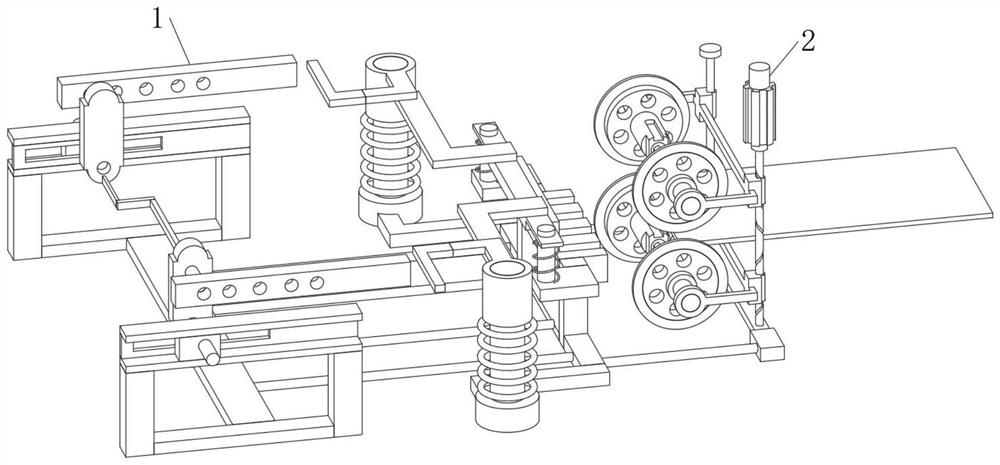
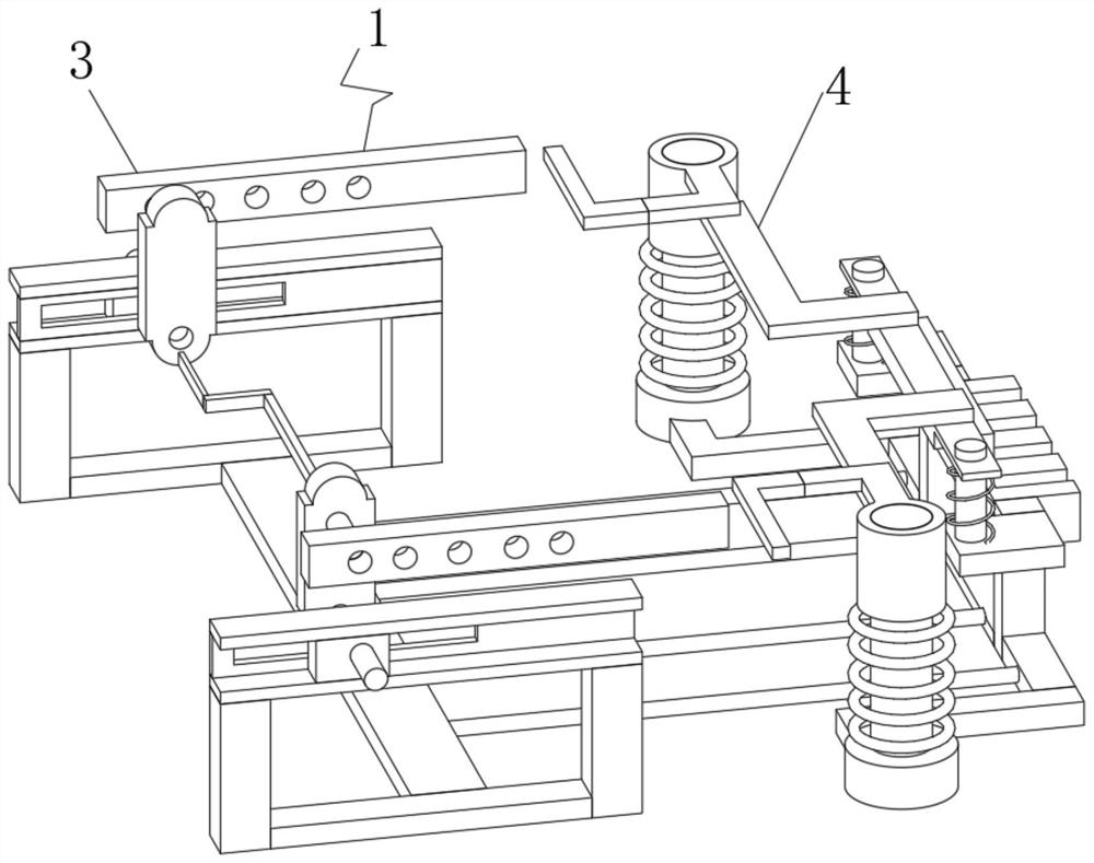
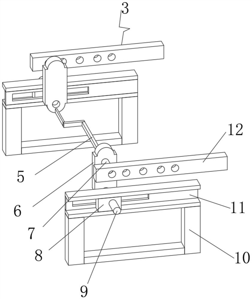
[0026] see Figure 1-5 , the present invention provides a technical solution: a shearing machine swing mechanism, including a contact conduction device 1, the side end position of the contact conduction device 1 is fixedly connected with a connection transmission device 2, by installing the contact conduction device 1, the contact conduction device 1 The inner end is composed of a contact structure 3 and a shear structure 4. The contact structure 3 can realize...


PUM


Abstract

The invention discloses a plate shearing machine swing mechanism which comprises a contact conduction device, the side end position of the contact conduction device is fixedly connected with a connection transmission device, the contact conduction device comprises a contact structure and a shearing structure, the contact structure is arranged on one side of the inner end of the contact conduction device, and the shearing structure is arranged on one side of the inner end of the contact conduction device. The shearing structure is fixedly connected to the side end position of the contact structure, the connecting transmission device comprises a first lantern ring, a first rotating ring, a transmission rod, a second lantern ring, a second rotating ring, a first threaded sleeve rod, a threaded guide rod, a motor, a second threaded sleeve rod and a smooth rod, and the motor is installed at the top of one side of the inner end of the connecting transmission device; the lower end of the motor is connected with a threaded guide rod in an inserted mode, and the top of the threaded guide rod is in threaded connection with a second threaded sleeve rod. According to the swing mechanism of the plate shearing machine, through the arrangement of the contact conduction device, the purpose of inner end contact conduction is achieved.

Description

technical field [0001] The invention relates to the technical field of shearing machine equipment, in particular to a shearing machine swing mechanism. Background technique [0002] According to Chinese Patent No. CN201520515122.4, the utility model discloses a swing mechanism of a shearing machine, which includes an upper shearing bed and a lower shearing bed. The lower shearing knife is matched with the cutter, and the upper shearing machine is located above the lower shearing machine. The lower end of the upper shearing machine is equipped with a swing mechanism. The swing mechanism includes a horizontal steel frame of the swing table. There is a swing support seat, and the steel frame of the swing table can rotate freely with the swing support seat as the fulcrum, and the other end of the steel frame of the swing table is provided with a supporting roller device; connection, the other end is provided with an upper pin, and the upper pin is perpendicular to the connectin...

Claims


Application Information

Patent Timeline
Patent Type & Authority Applications(China)
IPC IPC(8): B23D15/06B23D33/00
CPCB23D15/06B23D33/00
Inventor 张建成
Owner 张建成
Why Eureka
Try Eureka