Supercharge Your Innovation With Domain-Expert AI Agents!

Glue coating machine head

A machine head and glue coating technology, applied in the field of rubber products, can solve problems such as inconvenient disassembly

Pending Publication Date: 2022-03-01
MESNAC +1
View PDF0 Cites 0 Cited by
  • Summary
  • Abstract
  • Description
  • Claims
  • Application Information

AI Technical Summary

Problems solved by technology

[0004] The main purpose of the present invention is to provide a glue-coated machine head to solve the problem of inconvenient disassembly of the glue-coated machine head in the prior art

Method used


Image

  • Glue coating machine head
  • Glue coating machine head
  • Glue coating machine head

Examples


Embodiment Construction

[0027] It should be noted that, in the case of no conflict, the embodiments in the present application and the features in the embodiments can be combined with each other. The present invention will be described in detail below with reference to the accompanying drawings and examples.

[0028] In order to solve the problem of inconvenient disassembly of the glue-coated machine head in the prior art, the present invention provides a glue-coated machine head.

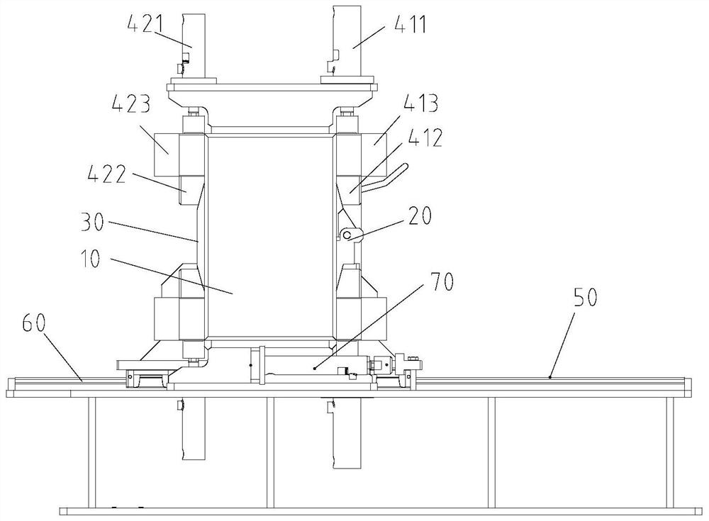
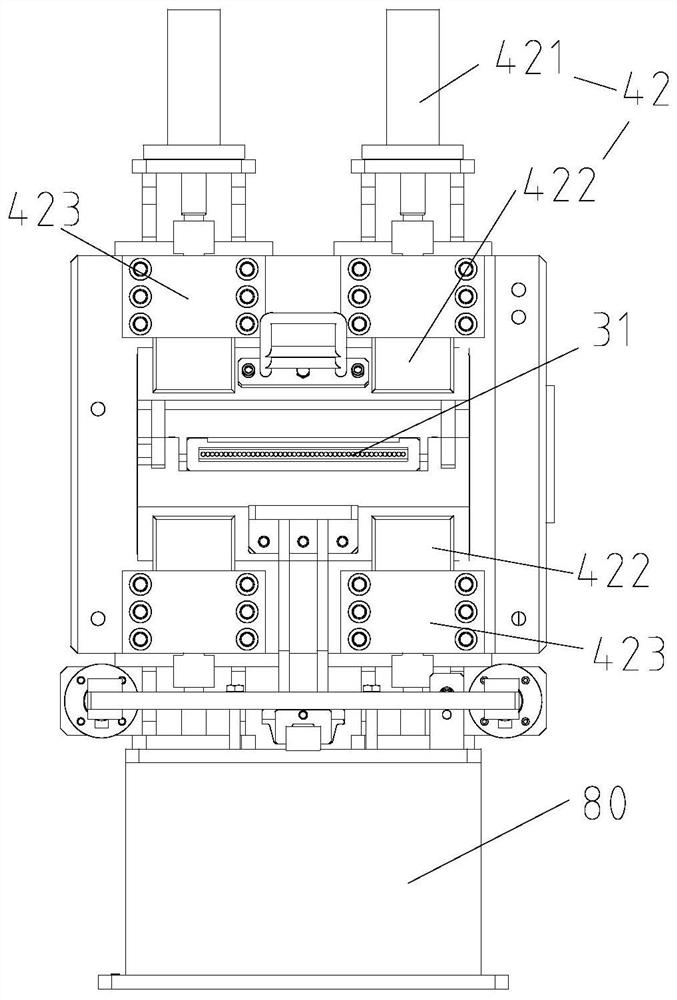
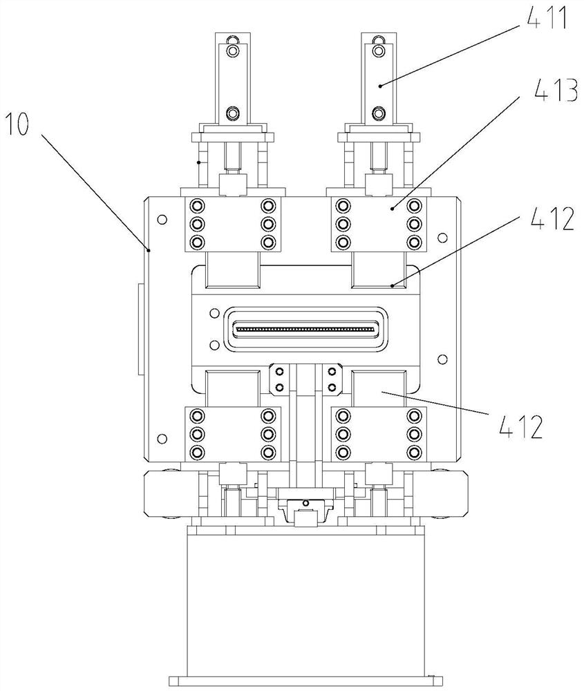
[0029] Please refer to Figure 1 to Figure 6 , the glue coating machine head is used for coating the surface of the substrate 90 with glue. The glue coating machine head includes: a body 10; a flow channel assembly 20, the flow channel assembly 20 is movably arranged relative to the body 10, wherein There is a material conveying channel 21 for conveying the base material 90 and a glue conveying channel 22 for conveying the rubber material; a die assembly 30, the die assembly 30 is connected with the runner assembly 20, a...


PUM


Abstract

The invention provides a glue coating machine head, which is used for coating glue on the surface of a base material, and comprises a machine body, the runner assembly is movably arranged relative to the machine body, and a material conveying channel used for conveying a base material and a glue conveying channel used for conveying glue are arranged on the runner assembly; the mouth-shaped assembly is connected with the runner assembly, and a material conveying opening is formed in the mouth-shaped assembly and used for outputting the glued base material; wherein the runner assembly and the mouth-shaped assembly are connected to define a gluing cavity, and the material conveying channel and the glue conveying channel are respectively communicated with the gluing cavity, so that a base material is glued in the gluing cavity. According to the glue coating machine head, the problem that a glue coating machine head in the prior art is inconvenient to disassemble is solved.

Description

technical field [0001] The invention relates to the technical field of rubber products, in particular to a rubber-coated machine head. Background technique [0002] At present, in the industry, the equipment for coating the surface of substrates such as steel wire / fiber fabrics generally uses a single-screw extruder to install a wide head, where the direction of glue output from the head (the direction of substrate advancement) is perpendicular to the direction of screw extrusion. It is convenient to clean the rubber material and install parts. The machine head is generally divided into left and right parts, which are connected by locking screws and nuts. Specifically, after the left and right machine head mold bodies slide or rotate to close the mold, screws are used to penetrate the left and right machine head molds. Body, tighten the nut to lock. [0003] For the above-mentioned connection structure, the connection method depends on the locking strength of each screw, wh...

Claims


Application Information

Patent Timeline
Patent Type & Authority Applications(China)
IPC IPC(8): B29C48/15B29C48/30
CPCB29C48/15B29C48/2562B29C48/2566
Inventor 刘树明宫一青吴元兴姜言青韩正霖
Owner MESNAC
Features
  • R&D
  • Intellectual Property
  • Life Sciences
  • Materials
  • Tech Scout
  • Unparalleled Data Quality
  • Higher Quality Content
  • 60% Fewer Hallucinations
Learn More