Busbar expansion joint

A technology for expansion joints and busbars, applied in power lines, vehicle components, power rails, etc., can solve problems such as affecting the mechanical compensation function of the expansion joint, deformation of the expansion joint body, and endangering the safety of trains. The effect of small initial slip force and improved installation efficiency

Pending Publication Date: 2022-03-01
FURRERFREY ELECTRIFICATION (GUANGZHOU) LTD
View PDF0 Cites 0 Cited by
  • Summary
  • Abstract
  • Description
  • Claims
  • Application Information

AI Technical Summary

Problems solved by technology

In the rigid catenary section, when the pantograph enters the bottom of the overlapping area of ​​the body on both sides of the expansion joint, the pantograph is likely to collide with another contact wire, which may lead to bow scraping and endanger the safety of

Method used


Image

  • Busbar expansion joint
  • Busbar expansion joint
  • Busbar expansion joint

Examples


Embodiment Construction

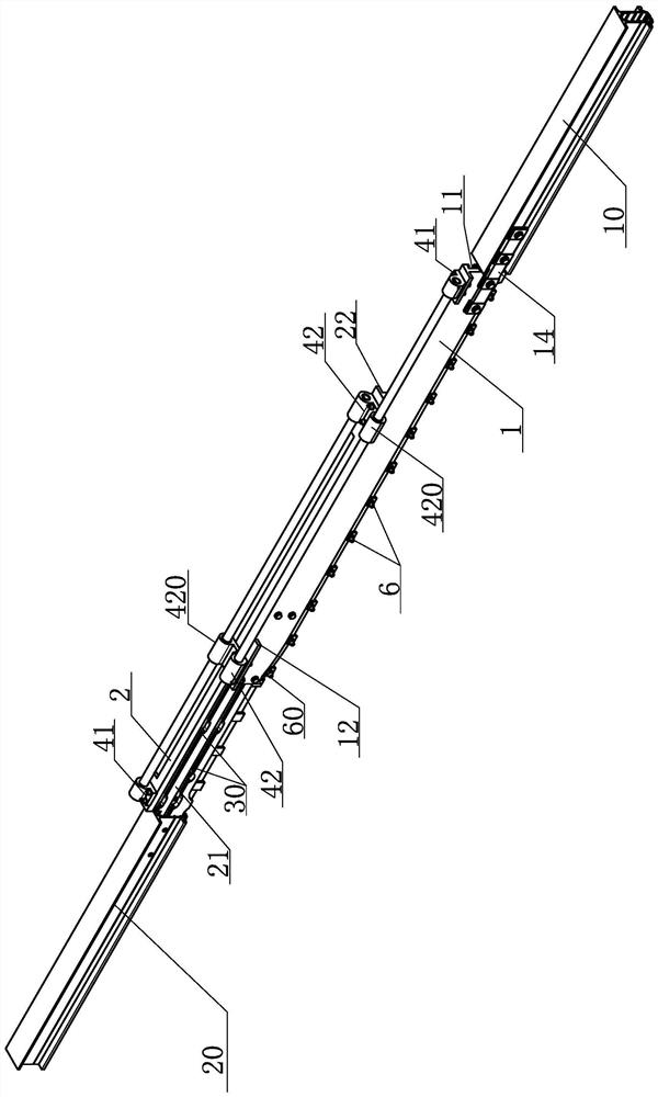
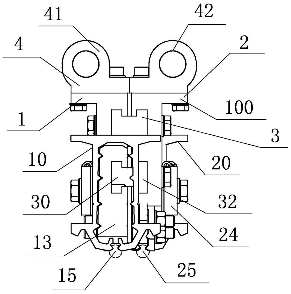
[0043] see Figure 1-Figure 2 As shown, a schematic diagram of the structure of an embodiment of the expansion joint of the bus bar according to the present invention is connected to the bus bar. The expansion joint mainly includes a deflector plate and an electrical connection device 4 . The deflectors are divided into a left deflector 1 and a right deflector 2 which have the same structure and are arranged side by side with the inner sides facing each other at intervals. The left deflector 1 includes a first end 11 and a second end 12 opposite to each other. The first end 11 of the left deflector 1 is fixedly connected to the left bus bar 10; the right deflector 2 also includes opposite first ends 21 and second ends 22, and the first end 22 of the right deflector 2 One end 21 is fixedly connected to the bus bar 20 on the right; two (single or multiple) chutes extending to both ends are provided on the inner sides of the left deflector 1 and the right deflector 2 30, the chu...


PUM


Abstract

The invention relates to a busbar expansion joint, which is arranged between two sections of busbars which are longitudinally arranged along a line and are arranged in parallel at a fixed interval in a rigid contact network system, and is provided with a guide plate and an electric connection device, the inner side face of each flow guide plate is provided with a sliding groove extending towards the two ends, the inner side faces of the two flow guide plates are opposite, the two flow guide plates are arranged side by side at intervals, and a clamping structure capable of sliding relatively is formed between the two flow guide plates through guide sliding blocks embedded into the sliding grooves. The two sections of busbars are located at the two ends of the clamping structure respectively and fixedly connected to the different flow guide plates respectively; the electric connection device is arranged on the top or the side face of the clamping structure and electrically connects the two flow guide plates. By adopting the expansion joint structure, a mechanical gap generated by thermal expansion and cold contraction at the joint of the busbars at the two ends can be effectively compensated, stable transition and continuous current taking can be achieved when a pantograph passes through the expansion joint structure, and it is ensured that the dynamic performance of a pantograph net meets the current collection standard requirement of the pantograph net.

Description

technical field [0001] The invention belongs to the technical field of rail transit traction power supply catenary, and in particular relates to a busbar expansion joint. Background technique [0002] In the rail transit rigid suspension power supply system, the expansion joint of the bus bar is connected in series between the bus bars of the two anchor sections, and is used as a mechanical compensation and electrical connection device for the length change of the bus bar due to thermal expansion and contraction. Compensation and adjustments are made for changes in the gaps of the busbars at both ends, and its electrical and mechanical properties need to ensure the seamless and smooth passage of the pantograph and meet the overall system indicators. [0003] When the rigid catenary system runs at high speed, the flatness of the pantograph-catenary contact surface has a direct impact on the pantograph-catenary relationship, so the rigid catenary has high requirements on the p...

Claims


Application Information

Patent Timeline
IPC IPC(8): B60M1/24B60M1/26
CPCB60M1/24B60M1/26B60M1/30B60M1/305B60M1/307B60L2200/26B60Y2200/30
Inventor B·富雷尔林锡荣王北维
Owner FURRERFREY ELECTRIFICATION (GUANGZHOU) LTD
Why Eureka
Try Eureka