
Cavel structure for front auxiliary frame and front auxiliary frame
A front sub-frame and horn technology, applied in the substructure, steering mechanism, vehicle components, etc., can solve the life safety hazards of drivers and passengers, and achieve the effect of protecting life safety and ensuring a stable connection
Patent Information
- Authority / Receiving Office
- CN · China
- Patent Type
- Applications(China)
- Current Assignee / Owner
- Publication Date
- 2022-03-01
Smart Images
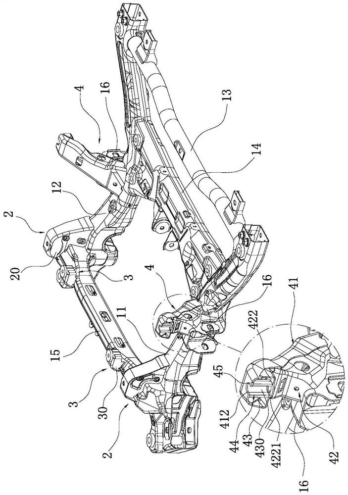
Figure 1 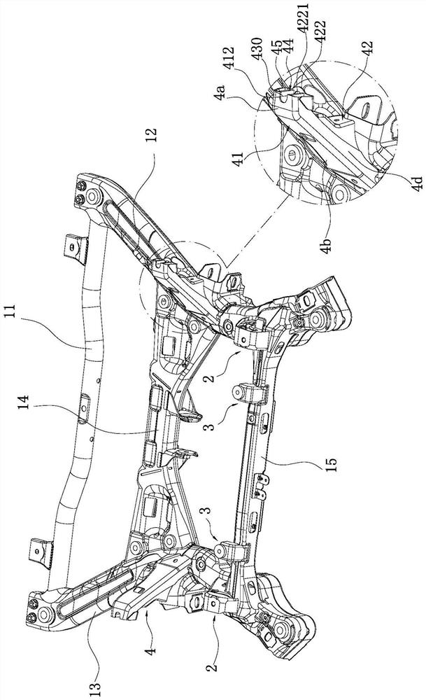
Figure 2 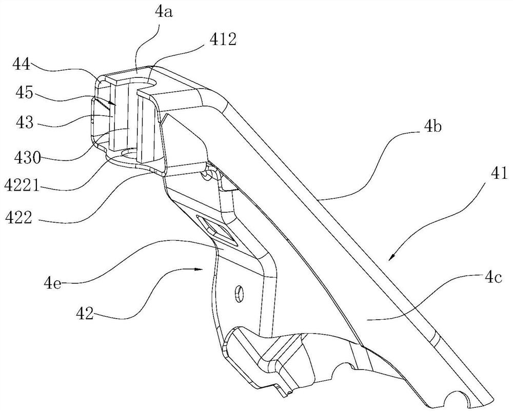
Figure 3
Abstract
Description
technical field
[0001] The invention relates to the field of automobile chassis components, in particular to a horn structure used for a front auxiliary frame and the front auxiliary frame. Background technique
[0002] The front sub-frame is the skeleton of the front and rear axles and an important part of the car chassis. Its main function is to reduce the impact of road vibration on the car body, improve the connection stiffness of the suspension system, and improve the comfort and stability of the car during driving. In addition, the sub-frame can also reduce the noise caused by the engine and road vibration, and improve the quiet level of the car cabin.
[0003] Furthermore, the front sub-frame and the body are connected by a six-point structure, and the middle mounting point between the sub-frame and the body adopts a croissant structure. For example, the patent number is ZL 201921833169.X (authorized announcement number is CN211494231U) of the Chinese utility model p...
Examples
Embodiment Construction
[0029] The present invention will be further described in detail below in conjunction with the accompanying drawings and embodiments.
[0030] In describing the present invention, it should be understood that the terms "center", "longitudinal", "transverse", "length", "width", "thickness", "upper", "lower", "front", " Back", "Left", "Right", "Vertical", "Horizontal", "Top", "Bottom", "Inner", "Outer", "Clockwise", "Counterclockwise", "Axial", The orientation or positional relationship indicated by "radial", "circumferential", etc. is based on the orientation or positional relationship shown in the drawings, and is only for the convenience of describing the present invention and simplifying the description, rather than indicating or implying the referred device or element must have a particular orientation, be constructed, and operate in a particular orientation, and since the disclosed embodiments of the invention may be arranged in different orientations, these directional te...