Turnover mechanism with self-locking function

A flipping mechanism and self-locking technology, applied in the pivot connection and other directions, can solve the problems of time-consuming and laborious, reduce the practicability of the flipping mechanism, hand injuries, etc., and achieve the effect of preventing hand injuries, improving practicability, saving time and labor.

Active Publication Date: 2022-03-01
襄阳众立弘业机电有限公司
View PDF5 Cites 0 Cited by
  • Summary
  • Abstract
  • Description
  • Claims
  • Application Information

AI Technical Summary

Problems solved by technology

[0006] Aiming at the deficiencies of the prior art, the present invention provides an overturning mechanism with a self-locking function, which has the advantage of automatic locking, and solves the problem of the need for manpower to adjust the supporting parts of the overturning structure to support intelligent devices such as computers, and is used by passengers. It is easy to injure the hand when adjusting the support by hand, and it is time-consuming and labor-intensive, thereby reducing the practicality of the turning mechanism

Method used


Image

  • Turnover mechanism with self-locking function
  • Turnover mechanism with self-locking function
  • Turnover mechanism with self-locking function

Examples


Embodiment 1

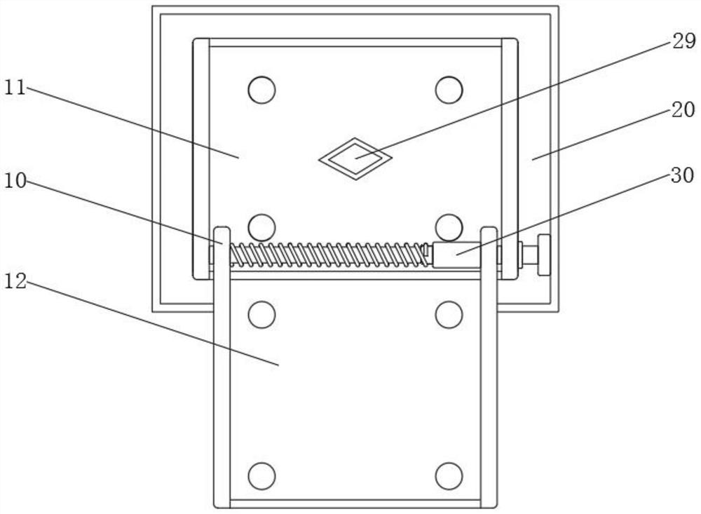
[0036] A kind of overturning mechanism with self-locking function, comprises overturning assembly 10, and overturning assembly 10 comprises fixed block 11, and the outer wall of fixed block 11 is fixedly connected to the inner side wall of mounting base 21 by the turntable 24 of installation, and one end of fixed block 11 Rotation is connected with turning block 12;

[0037] The interior of fixed block 11 is equipped with self-locking assembly 30, and self-locking assembly 30 comprises back-moving spring 31, and one end of back-moving spring 31 is fixedly connected with spring plunger 32, and one end of spring plunger 32 is fixedly connected with locking block 33, locking One side of the block 33 is fixedly connected with a push block 34, and one side of the push block 34 is slidably connected with a locking groove 35. One end of the locking groove 35 is provided with a circular hole, and the other end is provided with a curved hole smaller than the circular hole. Shaped hole ...

Embodiment 2

[0040] The installation function is added on the basis of the first embodiment.

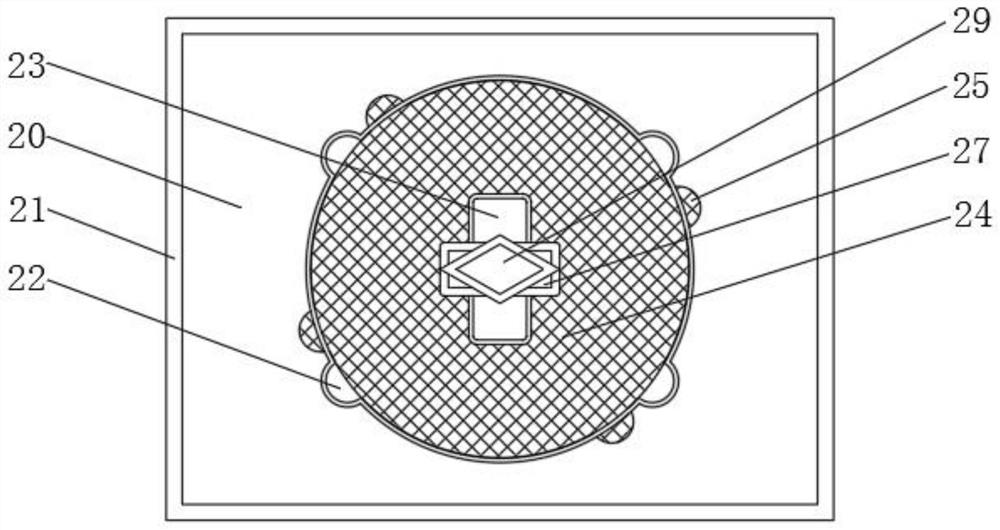
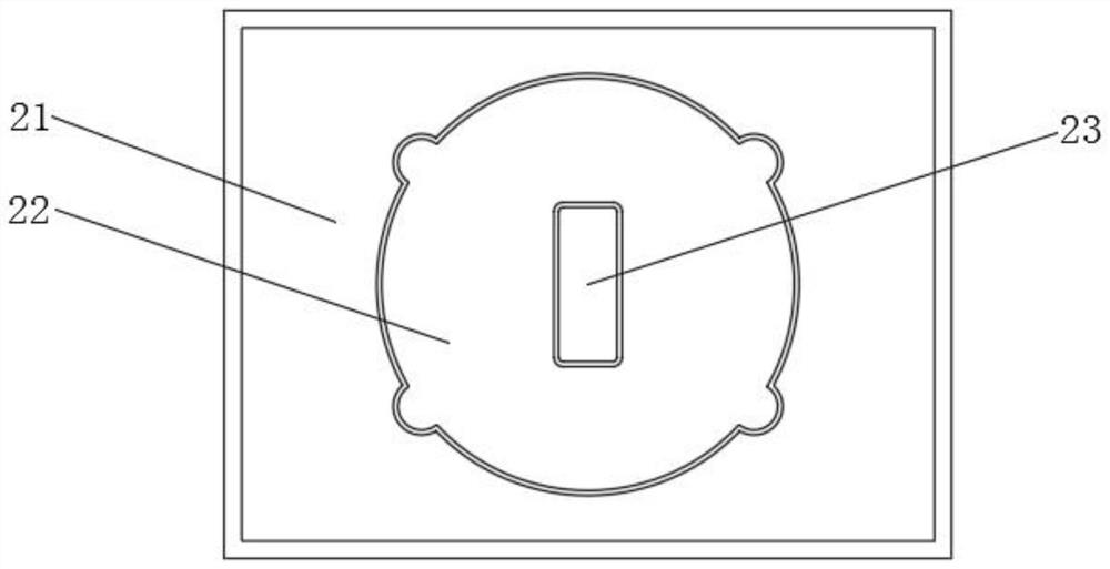
[0041] The outer wall of the fixed block 11 is provided with a mounting assembly 20, the mounting assembly 20 includes a mounting seat 21, the inner wall of the mounting seat 21 is provided with a mounting groove 22, and the middle part of the mounting groove 22 is provided with a limiting groove 23, and the limiting groove 23 is a kind of Rectangular slot, the limiting block 27 is a kind of rectangular block, the rectangular slot is longer than the rectangular block, the width of the rectangular slot is equal to the rectangular block, and one side of the limiting block 27 is clamped at the groove of the limiting slot 23 , the outer wall of the fixed block 11 is equipped with a turntable 24, the four vertices of the turntable 24 are respectively provided with a protrusion 25, the protrusion 25 is a semicircular protrusion, and the four vertices of the mounting groove 22 are respectively provided w...


PUM


Abstract

The invention relates to the technical field of turnover mechanisms, and discloses a turnover mechanism with a self-locking function, the turnover mechanism comprises a turnover assembly, the turnover assembly comprises a fixing block, one end of the fixing block is rotatably connected with a turnover block, a self-locking assembly is installed in the fixing block, the self-locking assembly comprises a reset spring, and the reset spring is connected with the turnover block. One end of the reset spring is fixedly connected with a spring plunger, one end of the spring plunger is fixedly connected with a locking block, and one side of the locking block is fixedly connected with a push block. The push block pushes the locking block to enter the circular hole groove of the locking groove and then pushes the push block to drive the locking block to move into the bent hole groove of the locking groove, so that the locking block is firmly clamped to the bent hole groove of the locking groove, the automatic locking effect is achieved, and the situation that a supporting piece of an overturning structure needs to be manually adjusted to support intelligent equipment such as a computer is avoided; and the situation that the hands of a passenger are injured when the passenger adjusts the supporting piece with the hands is prevented, time and labor are saved, and therefore the practicability of the turnover mechanism is improved.

Description

technical field [0001] The invention relates to the technical field of overturning mechanisms, in particular to an overturning mechanism with a self-locking function. Background technique [0002] The flip mechanism with self-locking function is a mechanical device used to connect two solids and allow relative rotation between the two. It can be composed of movable components or foldable materials. The tilting, Limiting and locking mechanism. [0003] At present, smart devices such as computers are installed in ships and cars. Due to the small space inside ships and cars, smart devices such as computers need to be supported by foldable brackets for the convenience of passengers. [0004] The existing overturning mechanism has a simple structure and a single function, and cannot achieve the self-locking function. It requires manpower to adjust the supports of the overturning structure to support smart devices such as computers. When the passengers adjust the supports by hand...

Claims


Application Information

Patent Timeline
IPC IPC(8): F16C11/04F16C11/10
CPCF16C11/04F16C11/10
Inventor 陈卫华方应海严维长王德明王重夺
Owner 襄阳众立弘业机电有限公司
Why Eureka
Try Eureka