High speed ball shear machine

Active Publication Date: 2010-12-02
YUAN ZE UNIV
View PDF5 Cites 3 Cited by
  • Summary
  • Abstract
  • Description
  • Claims
  • Application Information

AI Technical Summary

Benefits of technology

[0024]In light of the foregoing, in search of the metal bumps inside the machine, the metal bump catcher of the present invention allows the direct collection of the m

Problems solved by technology

However, solder joints have long been recognized to be the weakest link within an electronic product.
Any failure in one solder joint can make the whole package un-operated.
However, under the high speed ball shearing, the cracked metal bump drops into the inside of the machine due to the impact of the shear knife

Method used


Image

  • High speed ball shear machine
  • High speed ball shear machine
  • High speed ball shear machine

Examples


Example

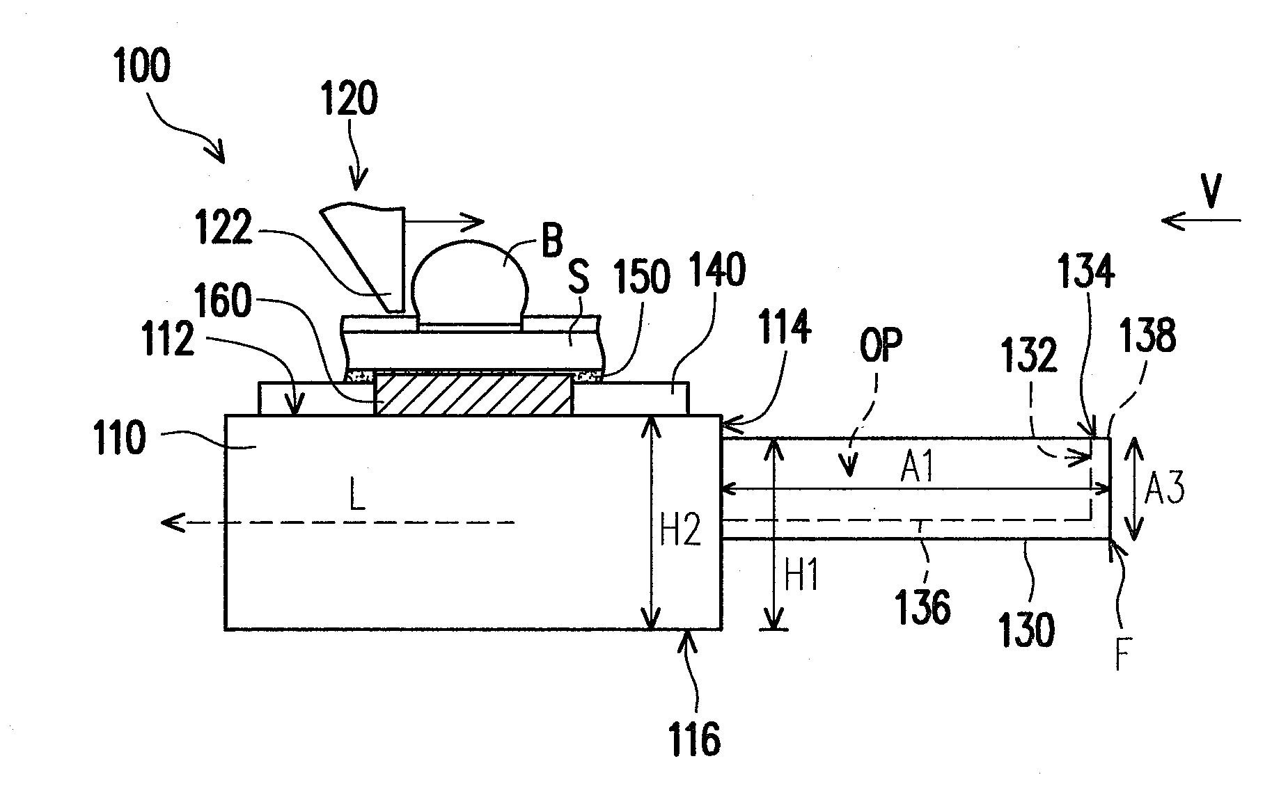
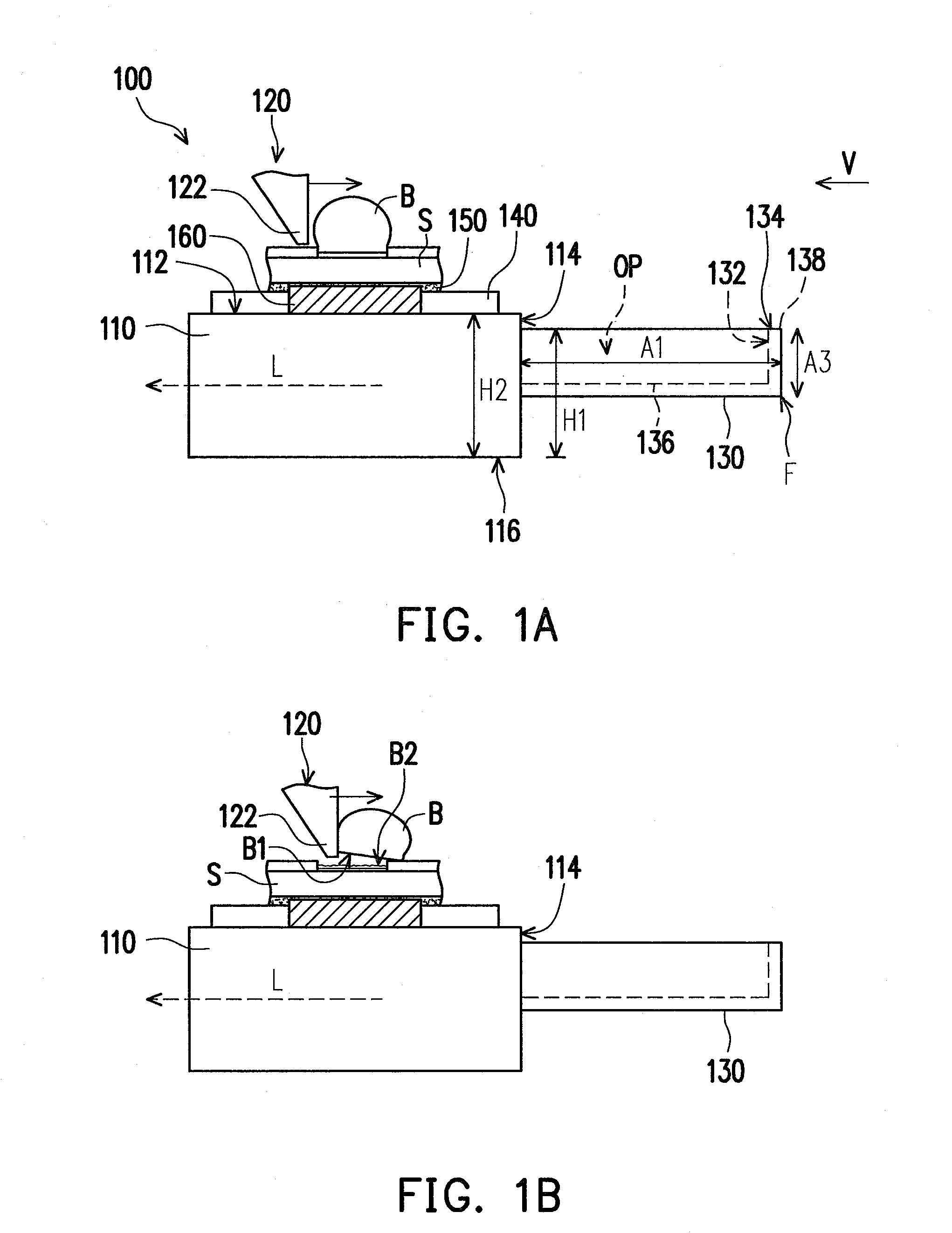
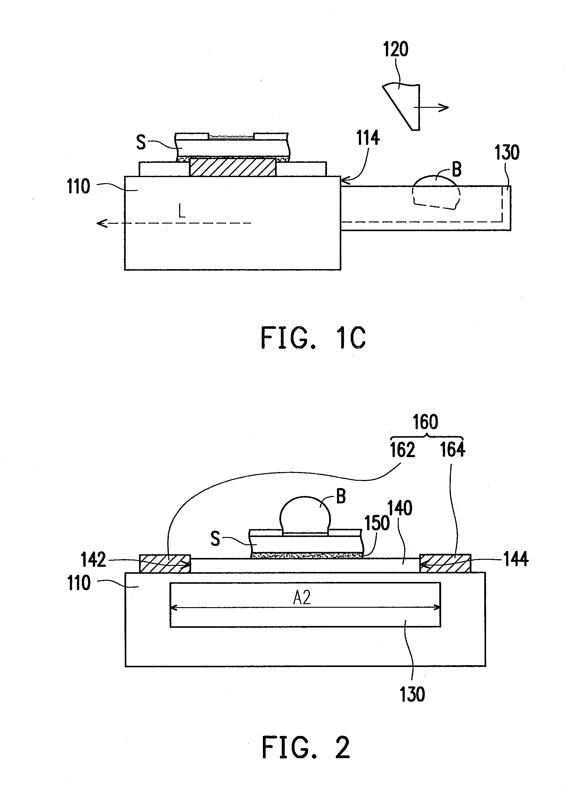
[0032]FIGS. 1A through 1C are schematic diagrams illustrating a high speed ball shear machine in a ball shearing process according to one embodiment of the present invention. FIG. 2 is a schematic diagram illustrating a fixing base and a metal bump catcher of the high speed ball shear machine in FIG. 1A from a direction V. FIG. 3 and FIG. 5 are respectively schematic diagrams of two variation structures of the high speed ball shear machine in FIG. 1A. FIG. 4 is a schematic diagram illustrating a fixing base and a metal bump catcher of the high speed ball shear machine in FIG. 3 from a direction V. FIG. 6 is a schematic diagram illustrating a fixing base and a metal bump catcher of the high speed ball shear machine in FIG. 5 from a direction V.

[0033]Referring to FIG. 1A and FIG. 2 simultaneously, a high speed ball shear machine 100 of the present embodiment is adapted to remove a metal bump B fixed on a substrate S. Here, the metal bump B is an aluminum ball, for example. The high sp...


PUM

PropertyMeasurementUnit
Lengthaaaaaaaaaa
Widthaaaaaaaaaa
Heightaaaaaaaaaa

Abstract

A high speed ball shear machine is adapted for removing a metal bump fixed on a substrate. The high speed ball shear machine includes a fixing base, a shear tool, and a metal bump catcher. The substrate is fixed on the top surface of the fixing base. The shear tool is disposed above the top surface. The fixing base is adapted for being translated along a translation path relative to the shear tool, wherein the translation path is a straight path. When the fixing base translates along the path, the metal bump is driven to strike the shear tool so as to separate itself from the substrate. The metal bump catcher, which is adapted for catching the drop bump after the striking, is disposed on the side wall of the fixing base. The bump catcher has a fillister with a configuration depicted in the figures of this invention.

Description

CROSS-REFERENCE TO RELATED APPLICATION[0001]This application claims the priority benefit of Taiwan application serial no. 98118041, filed Jun. 1, 2009. The entirety of the above-mentioned patent application is hereby incorporated by reference herein and made a part of specification.BACKGROUND OF THE INVENTION[0002]1. Field of the Invention[0003]The present invention relates to a high speed ball shear machine, and more particularly to a high speed ball shear machine capable of collecting dropping metal bumps.[0004]2. Description of Related Art[0005]Soldering is a key process for manufacturing solder joints, which is to apply an alloy with a lower melting point to joint two opposite materials together. The functions of solder joints are not only adopted as signal and electrical power passages between the devices, but also as the mechanical support during devices operation. According to recent International Roadmap for Semiconductor Technology announced by the Semiconductor Industry As...

Claims


Application Information

Patent Timeline
IPC IPC(8): B23K37/00B23K3/08
CPCB23K31/12B23K3/08
Inventor HO, CHENG-ENCHUNG, HAN-LIN
Owner YUAN ZE UNIV
Why Eureka
Try Eureka