
Test device for measuring flame tube cooling hole

A test device and cooling hole technology, which is applied in the direction of measuring device, engine test, machine/structural component test, etc., can solve the problem of not considering the initial cooling air film of airflow rotation, large error of test data, test transition section The accuracy of the test results is greatly affected, so as to facilitate real-time verification, reduce processing costs, and ensure accuracy

Pending Publication Date: 2022-03-01
AECC HUNAN AVIATION POWERPLANT RES INST
View PDF0 Cites 0 Cited by
  • Summary
  • Abstract
  • Description
  • Claims
  • Application Information

AI Technical Summary

Problems solved by technology

[0004] The current cooling hole flow field test device cannot be shared with the cooling efficiency test device, which greatly increases the cost of processing the test transition section and the complexity of the test process
And the above-mentioned cooling efficiency test device has the following defects: although the influence of the secondary flow of the two channels of the combustion chamber and the flow of the main flow of the flame tube is considered in the test process, the flow of the main flow does not consider the rotation of the head of the flame tube and the initial cooling air flow. The influence of the film, the heat conduction of the test transition section during the test has a great influence on the accuracy of the test results, and the air flow through the cooling holes on the test plate cannot be obtained directly, and two flowmeters need to be used to obtain it through indirect measurement. Subtract the mainstream inlet flow from the mainstream outlet flow, or subtract the secondary flow outlet flow from the secondary flow inlet flow. This way of obtaining the flow rate will lead to large errors in the test data.

Method used


Image

  • Test device for measuring flame tube cooling hole
  • Test device for measuring flame tube cooling hole
  • Test device for measuring flame tube cooling hole

Examples


Embodiment Construction

[0069] In order to make the purpose, technical solutions and advantages of the embodiments of the present invention more clear, the technical solutions in the embodiments of the present invention will be clearly and completely described below in conjunction with the accompanying drawings in the embodiments of the present invention. Obviously, the described embodiments It is a part of embodiments of the present invention, but not all embodiments. Based on the embodiments of the present invention, all other embodiments obtained by persons of ordinary skill in the art without making creative efforts belong to the protection scope of the present invention.

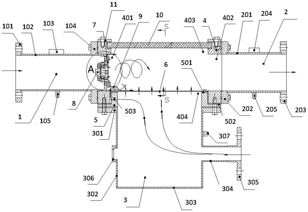
[0070] Such as figure 1 Shown, a kind of test device that the present invention proposes to measure the cooling hole of flame cylinder comprises:

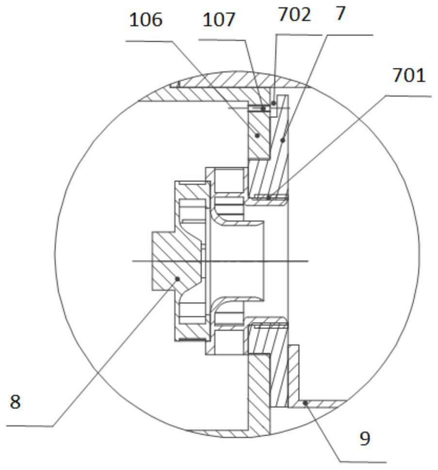
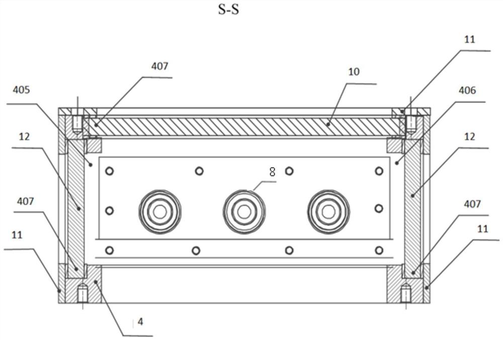
[0071] Mainstream intake assembly 1, exhaust assembly 2, secondary intake assembly 3, test case 4, support seat 5, test plate 6, vortex mount 7, vortex 8, cooling fin 9, glass 10,...


PUM


Abstract

The invention discloses a test device for measuring a flame tube cooling hole. The test device comprises a main flow air inlet assembly, an exhaust assembly, a secondary flow air inlet assembly, a test casing and a supporting seat, the mainstream air inlet assembly is installed on the test casing through bolts. The exhaust assembly is installed on the test casing through a bolt. The supporting seat is installed on a test casing through bolts. The secondary flow air inlet assembly is installed on one side of the supporting base through a bolt. According to the test device, the flow field characteristics and the cooling efficiency of the flame tube cooling hole can be measured; a swirler and a head air inlet are arranged, so that the flowing state of real mainstream rotational flow in the flame tube is simulated as much as possible; the initial cooling air flow forms a wall-attached cooling air film after passing through a slot formed between the cooling sheet and the test plate, and the flowing state of the real main flow in the flame tube is simulated; and a lead mounting seat is arranged, so that wall temperature data measured by the thermal infrared imager can be conveniently verified in real time.

Description

technical field [0001] The invention belongs to the technical field of aero-engine tests, in particular to a test device for measuring cooling holes of a flame tube. Background technique [0002] With the continuous improvement of aero-engine performance requirements, the inlet temperature and temperature rise of the combustion chamber continue to increase, and the cooling of the flame tube has attracted more and more attention from researchers, because it will affect the service life of the combustion chamber. The flow field characteristic analysis and cooling efficiency measurement of the cooling structure or cooling hole of the flame tube are the main channels to study the cooling problem of the flame tube. Through the analysis of the flow field characteristics, the cooling mechanism of the cooling structure or the cooling hole can be explored, so as to deeply explore the cooling potential. The cooling efficiency is an index to measure the cooling effect of a cooling stru...

Claims


Application Information

Patent Timeline
Patent Type & Authority Applications(China)
IPC IPC(8): G01M15/02G01D21/02
CPCG01M15/02G01D21/02
Inventor 段小瑶张德宝李彩云刘丽娟涂波张帆赵鸿华
Owner AECC HUNAN AVIATION POWERPLANT RES INST
Learn More