Grounding wire device for power grid maintenance and grounding condition monitoring method thereof
A technology of grounding wire and power grid, which is applied in the direction of grounding resistance measurement, circuit, connection, etc., can solve the problems of easy misjudgment, danger of operator electric shock, and high subjectivity, so as to improve work efficiency, avoid personnel electric shock, and realize The effect of electrometry and resistance value monitoring
- Summary
- Abstract
- Description
- Claims
- Application Information
AI Technical Summary
Problems solved by technology
Method used
Image

Examples
Embodiment 1
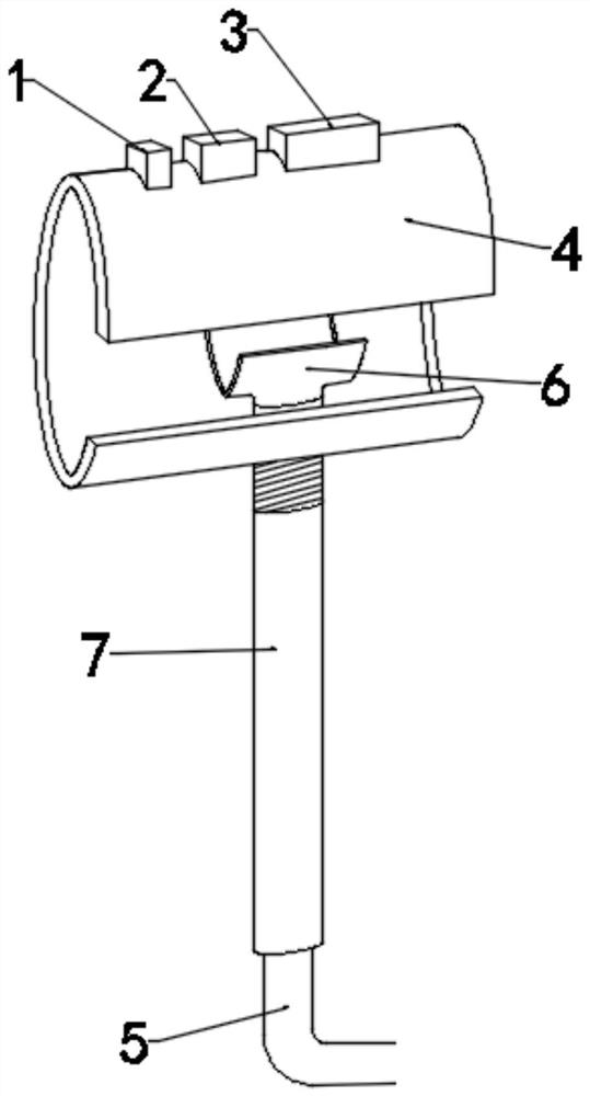
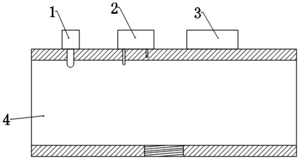
[0056] Such as Figure 1 to Figure 10 As shown, the present invention is a grounding wire device for power grid maintenance, including electrotest equipment 1, resistance monitoring equipment 2, position monitoring equipment 3, transmission line hook 4, grounding wire 5, cable pressing member 6 and operating rod 7, The electroscope 1, the resistance monitoring equipment 2 and the position monitoring equipment 3 are all arranged on the power line hook 4, and when the power line hook 4 is hooked to the power line, the electrical connection contact of the electroscope 1 In contact with the transmission line; in this embodiment, by setting the electroscope 1, resistance monitoring equipment 2, and position monitoring equipment 3 on the transmission line hook 4, it is possible to monitor the electrification of the circuit, grounding resistance, The position of the grounding point is monitored in real time, and the safety and reliability of the grounding condition of the grounding w...
Embodiment 2
[0070] Such as figure 1 As shown, a grounding condition monitoring method using the grounding wire device includes the following steps:
[0071] Step 1: Normal resistance value R 1 To determine, use resistance monitoring equipment 2 on the ground to measure the resistance value R under normal ground connection conditions before operation 1 , and set the normal resistor value R 1 Enter the smart terminal;
[0072] Step 2: Connect the power line hook 4 and conduct an electrical test to determine R 1 Finally, the transmission line hook 4 is sent to the power transmission line through the operating rod 7 and hooked up. After the hooking is completed, the electrical inspection equipment 1 works to perform an electrical inspection operation on the power grid;
[0073] Step 3: Ground and obtain the real-time resistance value R 2 and the location information of the mounting point, after the electric inspection operation is completed, the transmission line grounding operation is p...
Embodiment 3
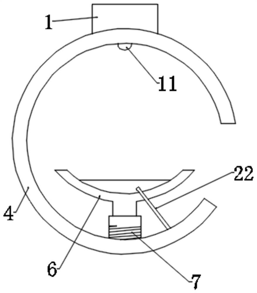
[0085] On the basis of Embodiment 1, this embodiment provides a replaceable connection structure between the cable pressing member 6 and the operating rod 7 and a power line grounding method using this structure. The replacement structure provided in this embodiment is mainly for In Embodiment 1, during the process of grounding the cable pressing member 6 against the transmission line by rotating the operating lever 7, the cable pressing member 6 may be deflected following the rotation of the operating lever 7, thus causing the cable pressing member 6. It cannot be effectively connected to the power line to realize grounding. Such as Figure 11 As shown, this replacement structure also includes a cable pressing member 6 and an operating rod 7, the difference is that a push rod 8 is added in the operating rod 7, and the top of the pushing rod 8 is connected to the pressing cable member 6, and the The bottom end of the ejector rod 8 protrudes from the operating rod 7; When pe...
PUM
 Abstract
Description
Claims
Application Information
 - R&D
- Intellectual Property
- Life Sciences
- Materials
- Tech Scout
- Unparalleled Data Quality
- Higher Quality Content
- 60% Fewer Hallucinations
Browse by: Latest US Patents, China's latest patents, Technical Efficacy Thesaurus, Application Domain, Technology Topic, Popular Technical Reports.
© 2025 PatSnap. All rights reserved.Legal|Privacy policy|Modern Slavery Act Transparency Statement|Sitemap|About US| Contact US: help@patsnap.com