Backward centrifugal fan and design method thereof

A centrifugal fan and fan technology, applied in mechanical equipment, liquid fuel engines, pumps, etc., can solve the problems of noise, backward centrifugal fan boundary layer separation, backward centrifugal fan shedding vortex, etc., to reduce fan noise and reduce separation. Vortex and trailing edge shedding vortex, the effect of improving operating efficiency

Pending Publication Date: 2022-03-01
JILIN UNIV
View PDF0 Cites 0 Cited by
  • Summary
  • Abstract
  • Description
  • Claims
  • Application Information

AI Technical Summary

Problems solved by technology

It has the characteristics of high static pressure and low air volume. In view of the shortcomings of low air volume, the industry often uses the method of increasing the fan speed to increase the air volume, which brings a series of noise problems: for example, the backward centrifugal fan is running. It is easy to generate a shedding vortex at its trailing edge, which is an important source of noise, or the noise problem caused by the strong boundary layer separation caused by the backward centrifugal fan on the upper part of the wheel cover due to the traditional design method

Method used


Image

  • Backward centrifugal fan and design method thereof
  • Backward centrifugal fan and design method thereof
  • Backward centrifugal fan and design method thereof

Examples


Embodiment Construction

[0024] The technical solutions of the present invention will be further explained in the form of specific examples below. The following examples are only preferred modes of the present invention, and the desired technical effects of the present invention can be achieved within the scope of the present invention.

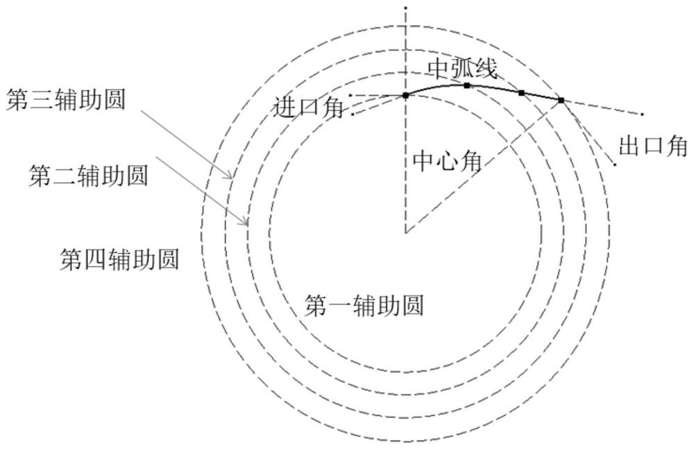
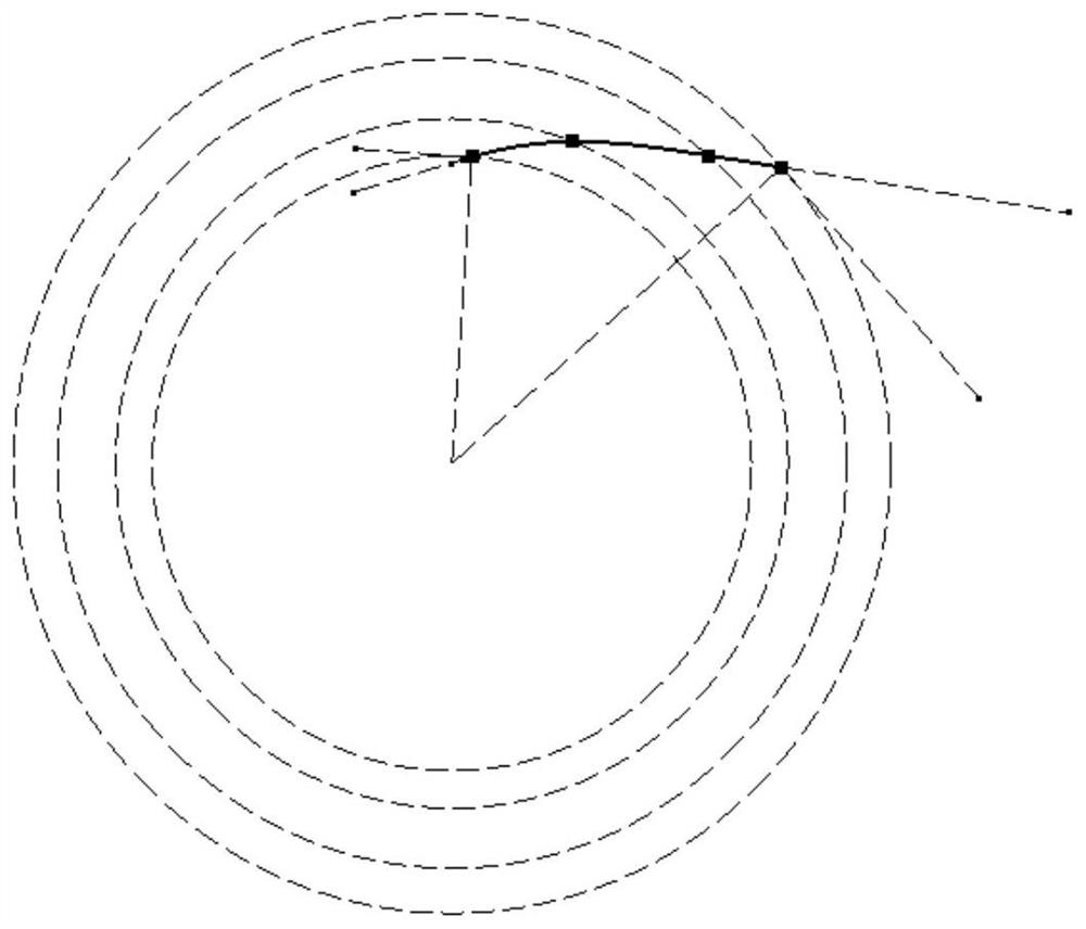
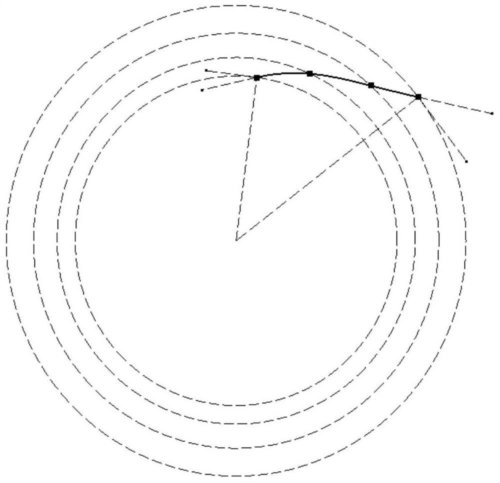
[0025] A kind of backward centrifugal fan, is made up of wheel bottom, wheel cover and fan blade between them, and described fan blade is divided into altogether 6 planes from wheel bottom to wheel cover and constitutes (such as Figure 13 ), define the plane at the bottom of the wheel as the first plane.

[0026] The fan blade intersects the plane to obtain the fan blade airfoil. The fan blade airfoil includes a central angle, an inlet angle, an outlet angle, and a middle arc. The middle arc of each fan blade airfoil is assisted by 4 circles. Lines are drawn, and the mid-arc is set as a spline during the design process. The circle where the starting point of the mi...


PUM


Abstract

The invention discloses a backward centrifugal fan and a design method thereof, and belongs to the field of backward centrifugal fan design, fan blades are divided into n planes from a wheel bottom to a wheel cover, the fan blades intersect with the planes to obtain fan blade airfoils, and the mean camber line of each fan blade airfoil is drawn by taking m concentric auxiliary circles as auxiliary lines, the ratio of the diameter of the first auxiliary circle to the diameter of the fan is greater than 1 / 2; the radius of the mean camber line designed by the other planes is larger than the radius of the starting point of the mean camber line designed by the first plane, the ratio of the difference between the radius of the starting point of the mean camber line of different planes and the radius of the starting point of the mean camber line of the first plane to the radius of the fan meets the formula requirement, and in all the planes, the central angle is (0.85-0.95) * 360 degrees / blade number; in the plane from the wheel bottom to the 2 / 3 fan blade height range, the outlet angle is kept within the range of 40-50 degrees, and in the plane exceeding the 2 / 3 fan blade height, the outlet angle needs to meet the formula requirement.

Description

technical field [0001] The invention belongs to the technical field of backward centrifugal fans. Background technique [0002] In the home appliance industry and fan industry, backward centrifugal fans are often used as the power source of the air supply system. It has the characteristics of high static pressure and low air volume. In view of the shortcomings of low air volume, the industry often uses the method of increasing the fan speed to increase the air volume, which brings a series of noise problems: for example, the backward centrifugal fan is running. It is easy to generate a shedding vortex at its trailing edge, which is an important source of noise, or the noise problem caused by the strong boundary layer separation caused by the backward centrifugal fan on the upper part of the wheel cover caused by the traditional design method. Contents of the invention [0003] For the problems referred to above, the technical scheme adopted in the present invention is spe...

Claims


Application Information

Patent Timeline
Patent Type & Authority Applications(China)
IPC IPC(8): G06F30/17F04D29/30
CPCG06F30/17F04D29/30
Inventor 田丽梅田伟商震徐浩然李百容
Owner JILIN UNIV
Why Eureka
Try Eureka