Conduction instrument test marking device and use method thereof

A marking device and conduction technology, which is applied in the direction of measuring device, marking, short-circuit test, etc., can solve the problems of high energy consumption, missing marking, affecting the quality of wire harness production, etc., and achieve the effect of convenient horizontal rotation adjustment.

Pending Publication Date: 2022-03-01
ANHUI NINGGUO TIANCHENG ELECTRICAL APPLIANCES
View PDF0 Cites 2 Cited by
  • Summary
  • Abstract
  • Description
  • Claims
  • Application Information

AI Technical Summary

Problems solved by technology

[0005] Aiming at the deficiencies of the prior art, the present invention provides a conductance meter test marking device and its use method, which solves the problem that when the conductance meter is used to test the wire harness, the staff usually holds a marking pen to test the completed wire harness. Manual marking process, when the staff works for a long time, it is easy to cause missing marks, and then it is easy to confuse the tested wiring harness with the untested wiring harness, which affects the production quality of the wiring harness, and the staff manually operates the working process of marking the wiring harness It is cumbersome, time-consuming, energy-intensive, and labor-intensive, resulting in a decrease in work efficiency

Method used


Image

  • Conduction instrument test marking device and use method thereof
  • Conduction instrument test marking device and use method thereof
  • Conduction instrument test marking device and use method thereof

Examples


Embodiment Construction

[0029] The following will clearly and completely describe the technical solutions in the embodiments of the present invention with reference to the accompanying drawings in the embodiments of the present invention. Obviously, the described embodiments are only some, not all, embodiments of the present invention. Based on the embodiments of the present invention, all other embodiments obtained by persons of ordinary skill in the art without making creative efforts belong to the protection scope of the present invention.

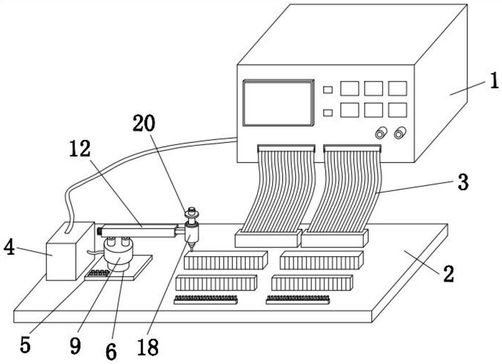
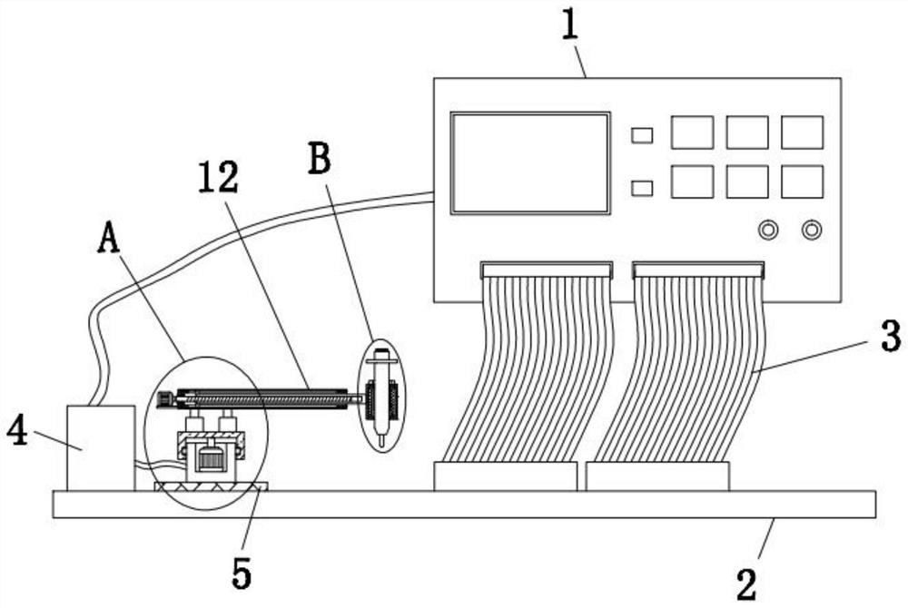
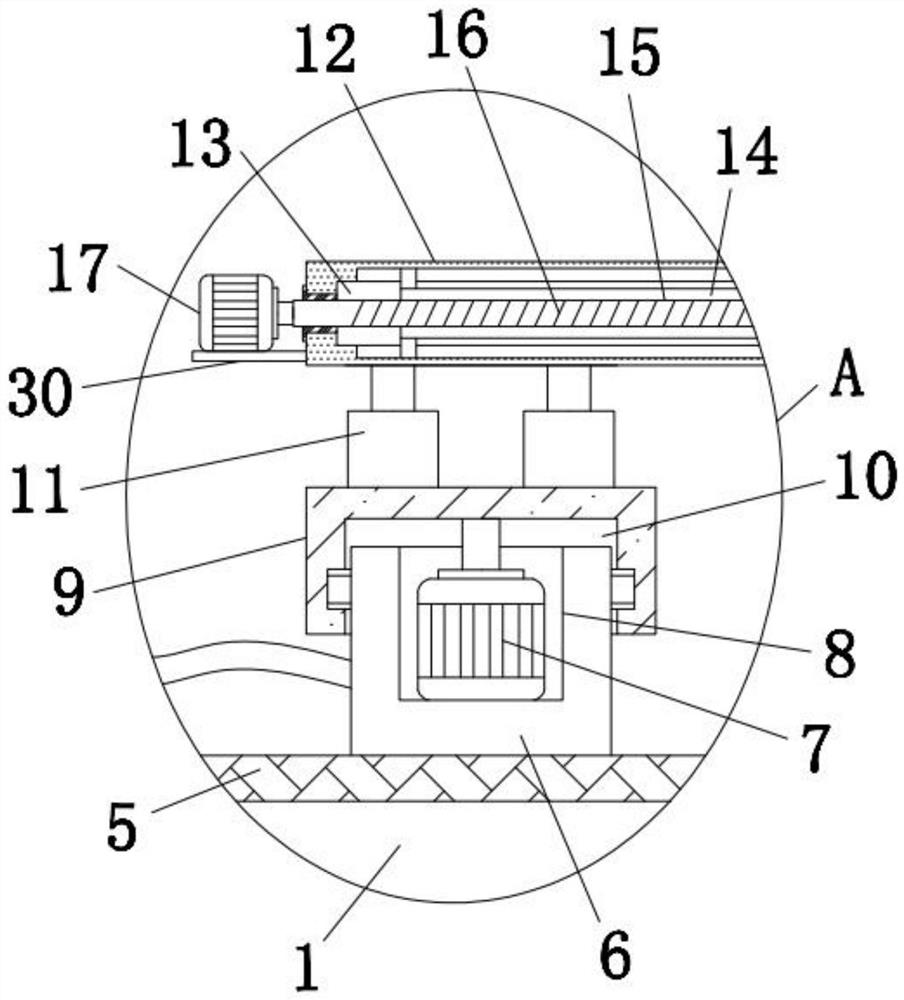
[0030] Such as Figure 1-5As shown, the present invention provides a technical solution: a conductance instrument test marking device, including a conductance instrument body 1, a test stand 2 and two test cables 3, by using the conductance instrument body 1, a test stand 2 and two The connection and coordination of the test cable 3 can carry out the conduction detection work on the wiring harness. One end of the two test cables 3 is connected to the front sid...


PUM


Abstract

The invention discloses a conduction instrument test marking device and a use method thereof.The conduction instrument test marking device comprises a conduction instrument body, a test board and two test flat cables, one end of each test flat cable is connected with the front side of the conduction instrument body, and the other end of each test flat cable is connected with the rear side of the conduction instrument body; the ends, away from the conduction instrument body, of the two testing flat cables are connected with the testing table, a control box and a bottom plate are fixedly installed at the top of the testing table, a stand column is fixedly installed at the top of the bottom plate, and a groove is formed in the top of the stand column. The wiring harness marking device is reasonable in design and good in practicability, can automatically mark a tested wiring harness, does not need manual marking of workers, saves time and labor, reduces the labor amount of the workers, does not generate a marking missing phenomenon, facilitates adjustment of the horizontal position and the height position of a marking pen, and improves the working efficiency. Wire harnesses of different sizes can be marked conveniently, and different positions on the wire harnesses can be marked conveniently according to needs.

Description

technical field [0001] The invention relates to the technical field of wiring harness testing, in particular to a conduction meter testing marking device and a method for using the same. Background technique [0002] The continuity tester is a portable tester with a high degree of automation, which is specially used for the electrical integrity test of the device. The built-in power supply of the continuity tester can convert the industrial voltage into a safe voltage. The actual use is weak current detection, which is not harmful to the user. There are safety problems. In the wire harness production and processing plant, the wire harness conductance tester is usually used to detect the conduction of the completed wire harness. The wire harness conduction tester plays a very important role in testing the quality and reliability of the wire harness. By using the instrument to detect, It can be found that there are short circuits and open circuits in the wiring harness. [00...

Claims


Application Information

Patent Timeline
IPC IPC(8): G09F7/20G01R31/52G01R31/54G01R31/58
CPCG09F7/20G01R31/52G01R31/54G01R31/58
Inventor 江盈汪洋陈启志
Owner ANHUI NINGGUO TIANCHENG ELECTRICAL APPLIANCES
Why Eureka
Try Eureka