Supercharge Your Innovation With Domain-Expert AI Agents!

Display panel and pixel circuit thereof

A pixel circuit and display panel technology, applied to static indicators, instruments, etc., can solve the problems of signal voltage conversion and loading, affecting optical effects, etc.

Pending Publication Date: 2022-03-01
AU OPTRONICS CORP
View PDF0 Cites 0 Cited by
  • Summary
  • Abstract
  • Description
  • Claims
  • Application Information

AI Technical Summary

Problems solved by technology

For example, current division affects optical effects, signal voltage conversion loading (loading) and other issues

Method used


Image

  • Display panel and pixel circuit thereof
  • Display panel and pixel circuit thereof
  • Display panel and pixel circuit thereof

Examples


Embodiment Construction

[0028] Below in conjunction with accompanying drawing, structural principle and working principle of the present invention are specifically described:

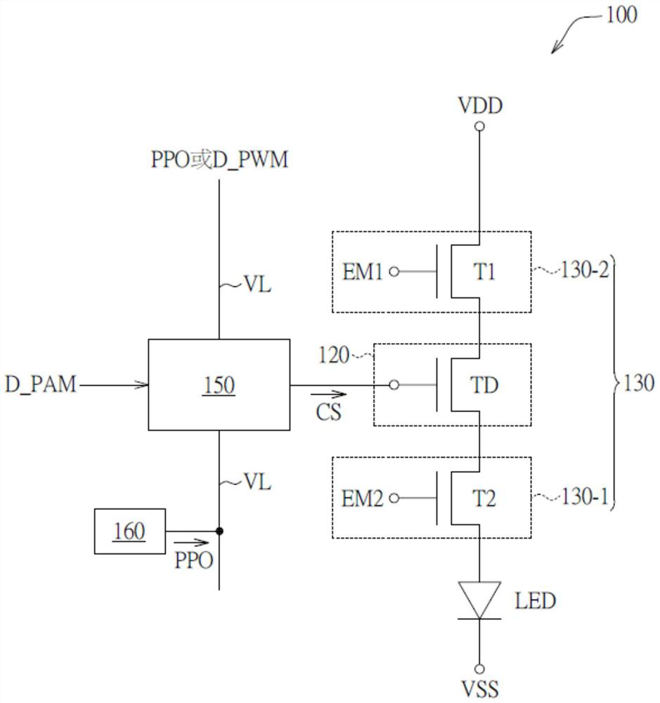
[0029] Please refer to figure 1 , figure 1 It is a block diagram of a pixel circuit according to an embodiment of the present invention. The pixel circuit 100 includes a driving unit 120 , a light emitting controller 130 , a light emitting element LED, a first driving block 150 and a second driving block 160 .

[0030] The driving unit 120 includes a driving transistor TD. The driving transistor TD has a control terminal for receiving a control signal CS, wherein the control signal CS may include a pulse width control signal and an amplitude control signal. The driving transistor TD generates a driving signal according to the control signal CS to drive the light emitting element LED to emit light. In this embodiment, the light emitting element LED may be any form of light emitting diode.

[0031] The circuits 130-1, 130-2...


PUM


Abstract

The invention provides a pixel circuit and a display panel. The pixel circuit comprises a driving unit, a light-emitting element and a light-emitting control circuit which are connected in series between a power supply voltage and a reference power supply; the first driving block is coupled to a control end of the driving unit and a vertical signal line, and is used for outputting a control signal to the driving unit according to a pulse width modulation signal and an amplitude modulation signal, and receiving a reference voltage from the vertical signal line at a light emitting time, receiving the pulse width modulation signal from the vertical signal line at a data writing time; and the second driving block is connected to the vertical signal line and is used for outputting the reference voltage to the first driving block through the vertical signal line at the light emitting time. The data writing time and the light emitting time form a frame.

Description

technical field [0001] The invention relates to a display panel and a pixel circuit thereof. Background technique [0002] The resolution of display devices is increasing day by day. An increase in resolution means an increase in scan lines. For high-resolution display devices, there are still some problems in the actual operation of the progressive scanning driving method. For example, current division affects optical effects, signal voltage conversion loading, and other issues. Therefore, it is necessary to improve the high-resolution display device and its driving method. Contents of the invention [0003] One aspect of the present invention provides a pixel circuit, including: a driving unit, a light-emitting element and a light-emitting control circuit connected in series between a power supply voltage and a reference power supply; a first driving block, coupled to the driving A control terminal and a vertical signal line of the unit are used to output a control s...

Claims


Application Information

Patent Timeline
IPC IPC(8): G09G3/30G09G3/32
CPCG09G3/30G09G3/32G09G2320/0247
Inventor 奚鹏博林振祺
Owner AU OPTRONICS CORP
Features
  • R&D
  • Intellectual Property
  • Life Sciences
  • Materials
  • Tech Scout
  • Unparalleled Data Quality
  • Higher Quality Content
  • 60% Fewer Hallucinations
Learn More