Supercharge Your Innovation With Domain-Expert AI Agents!

Valve clamp with sealing device

A sealing device and valve technology, applied in the field of valve clips, can solve the problems of difficulty in adjusting the opening and closing angle of the device, the large volume of the sealing device, and the damage of blood vessels, achieving good anti-reflux effect, good clinical significance, and solving technical pain points. Effect

Pending Publication Date: 2022-03-04
NINGBO JENSCARE BIOTECHNOLOGY CO LTD
View PDF1 Cites 0 Cited by
  • Summary
  • Abstract
  • Description
  • Claims
  • Application Information

AI Technical Summary

Problems solved by technology

[0012] One of the purposes of this application is to overcome the deficiencies of the prior art, for example, the sealing device on the valve clip is too large, the blood vessel will be damaged during the approach, and the stroke is too long, which makes it difficult to adjust the bending of the device and interfere with the valve clipping. A valve clip with a sealing device is provided to solve problems such as occlusal angles

Method used


Image

  • Valve clamp with sealing device
  • Valve clamp with sealing device
  • Valve clamp with sealing device

Examples


Embodiment 1

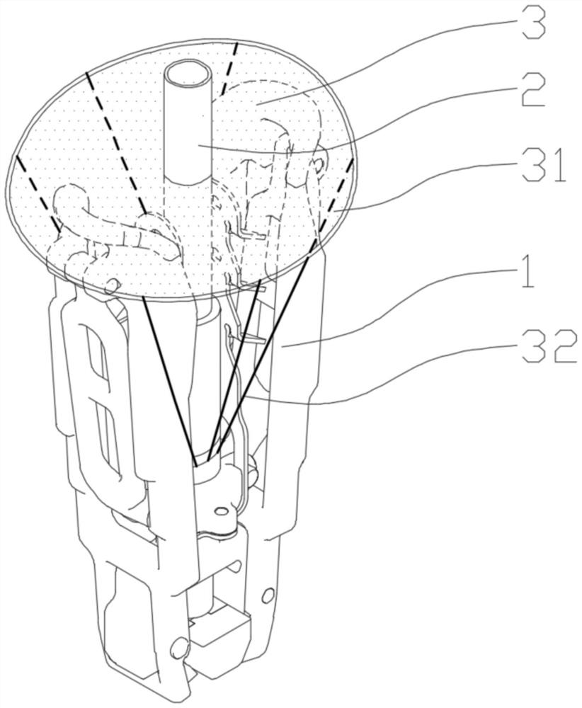
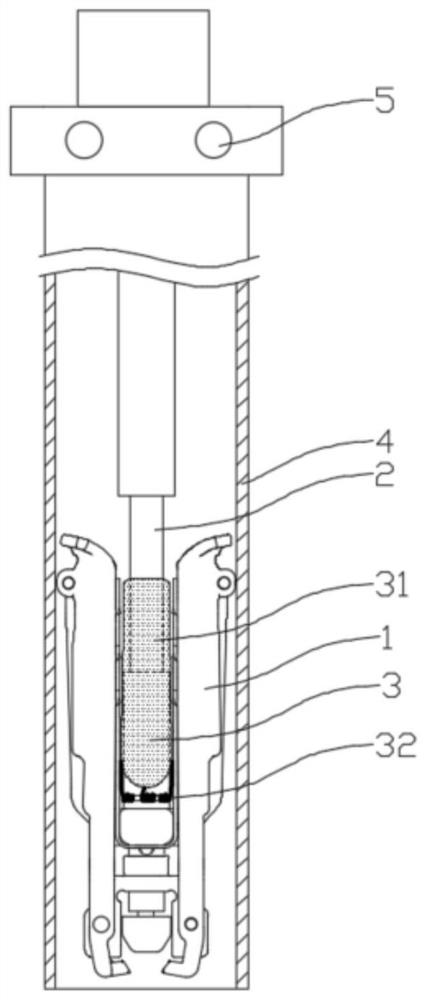
[0047] Such as figure 1 As shown, a sealing device 3 on a valve clip according to an embodiment of the present application is illustrated, including a clamping arm 1, a central rod 2 and a sealing device 3, and the sealing device 3 includes a blocking member 31 and a pulling member 32, the blocking member 31 is passed through the central rod 2, one end of the pulling member 32 is connected to the blocking member 31, the other end of the pulling member 32 is connected to the central rod 2, and the pulling The piece 32 can prevent the blocking piece 31 from flipping backwards, and the blocking piece 31 is a flexible piece; the flexible blocking piece 31 makes the valve clip not increase its loading diameter during pre-installation, and does not affect the delivery of the delivery instrument at the same time. When the bending operation.

[0048] In the first embodiment, when the valve clip is pre-installed, the blocking member 31 is attached to the central rod 2, which will not ...

Embodiment 2

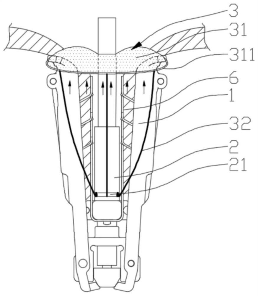
[0061] Embodiment 2 is basically the same as Embodiment 1, except that in this embodiment, the sealing device 3 is not provided with a pulling member 32 , but the sealing device 3 is fixed on the flap catching spring 6 .

[0062] In the second embodiment, a valve clip with a sealing device 3 includes a clamping arm 1, a leaflet capturing shrapnel 6, a central rod 2 and a sealing device 3, and the sealing device 3 is mounted on the central rod 2 , the sealing device 3 is connected with the leaflet catch shrapnel 6, such as Figure 5a with 5b As shown, and the sealing device 3 is a flexible member, the sealing device 3 is generally in a sheet-like structure in a natural state, and when the sealing device 3 is impacted by blood, it will be filled and generally assume an umbrella-like structure.

[0063] In the second embodiment, the sealing device 3 is folded between the central rod 2 and the leaflet catch spring 6 during pre-installation. Since the sealing device 3 is a flexibl...


PUM


Abstract

The invention relates to the field of medical instruments, in particular to a valve clamp with a sealing device, the valve clamp comprises a clamping arm, a center rod and the sealing device, the sealing device comprises a blocking piece and a traction piece, the blocking piece is arranged on the center rod in a penetrating mode, one end of the traction piece is connected with the blocking piece, and the other end of the traction piece is connected with the center rod; the blocking piece is a flexible piece; the blocking piece is a flexible sheet-shaped piece and can be attached to the center rod during preassembling, the loaded pipe diameter of the blocking piece cannot be increased, bending adjusting operation of a conveying instrument in a blood vessel cannot be affected, when blood regurgitates, the blood impacts the blocking piece to enable the blocking piece to bulge, the blood is blocked from flowing into the atrium, and meanwhile the blocking piece is prevented from being damaged. The flexible blocking piece does not interfere with the opening angle of the clamping arms when bulging, the good leakage-proof effect is achieved, meanwhile, the technical pain point existing in the prior art is solved, and good clinical significance is achieved.

Description

technical field [0001] The present application relates to the field of medical devices, in particular to a valve clip with a sealing device. Background technique [0002] The mitral valve is located at the left atrioventricular orifice and consists of five parts: the valve annulus, valve leaflets, chordae, papillary muscles, and junctional junction. Its anatomically accurate name is mitral valve apparatus (mitral apparatus) or mitral valve complex (mitral complex). [0003] The tricuspid valve is located at the right atrioventricular orifice and has three approximately triangular sail-shaped valves. The bottom of the valve is attached to the fibrous annulus of the atrioventricular orifice. Functionally, the fibrous annulus, valves, chordae and papillary muscles can be seen. It is a tricuspid valve. Valve complex (tricuspidvalvarcomplex). [0004] Mitral regurgitation (mitral regurgitation) can be divided into the following two types: 1. Rheumatic cardiac mitral regurgitati...

Claims


Application Information

Patent Timeline
IPC IPC(8): A61F2/24
CPCA61F2/2469A61F2/2442
Inventor 吴磊王陶赵月
Owner NINGBO JENSCARE BIOTECHNOLOGY CO LTD
Features
  • R&D
  • Intellectual Property
  • Life Sciences
  • Materials
  • Tech Scout
  • Unparalleled Data Quality
  • Higher Quality Content
  • 60% Fewer Hallucinations
Learn More