Concentricity detection equipment

A technology for testing equipment and concentricity, which is applied in the direction of measuring devices, mechanical measuring devices, instruments, etc., can solve the problems of instability, deviation, and low measurement efficiency of measurement results, and achieve stable rotation, simple operation, and high detection accuracy Effect

Pending Publication Date: 2022-03-08
厦门新瓷材料科技有限公司
View PDF0 Cites 0 Cited by
  • Summary
  • Abstract
  • Description
  • Claims
  • Application Information

AI Technical Summary

Problems solved by technology

The traditional coaxiality detector needs to manually place the workpiece on the workpiece support during measurement, and then adjust the three-dimensional translation stage to make the lens coaxial with the inner hole of the workpiece. During each measurement process, it is nece

Method used


Image

  • Concentricity detection equipment
  • Concentricity detection equipment
  • Concentricity detection equipment

Examples


Embodiment Construction

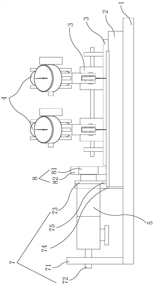
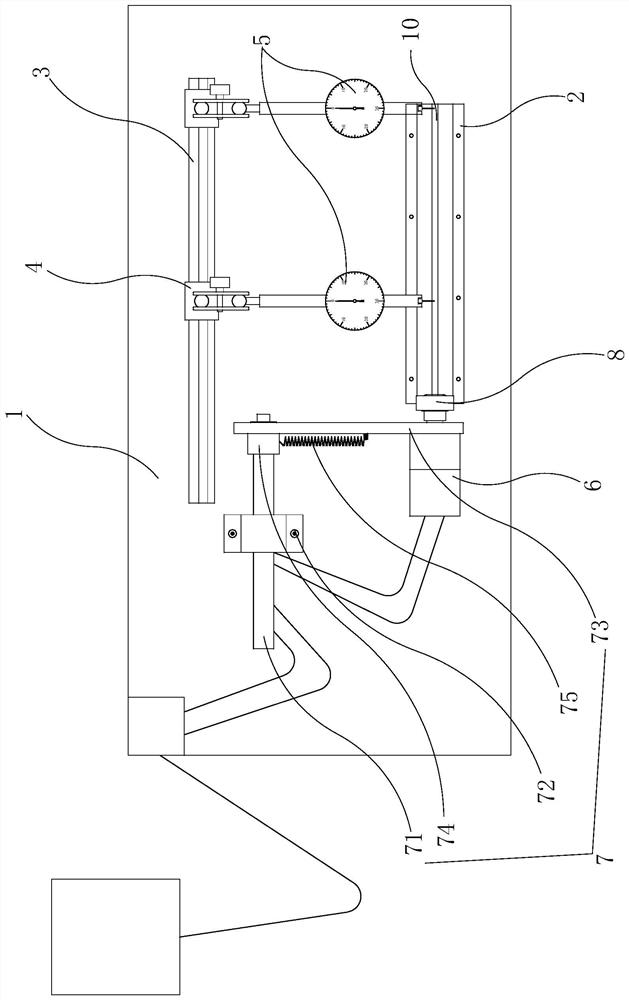
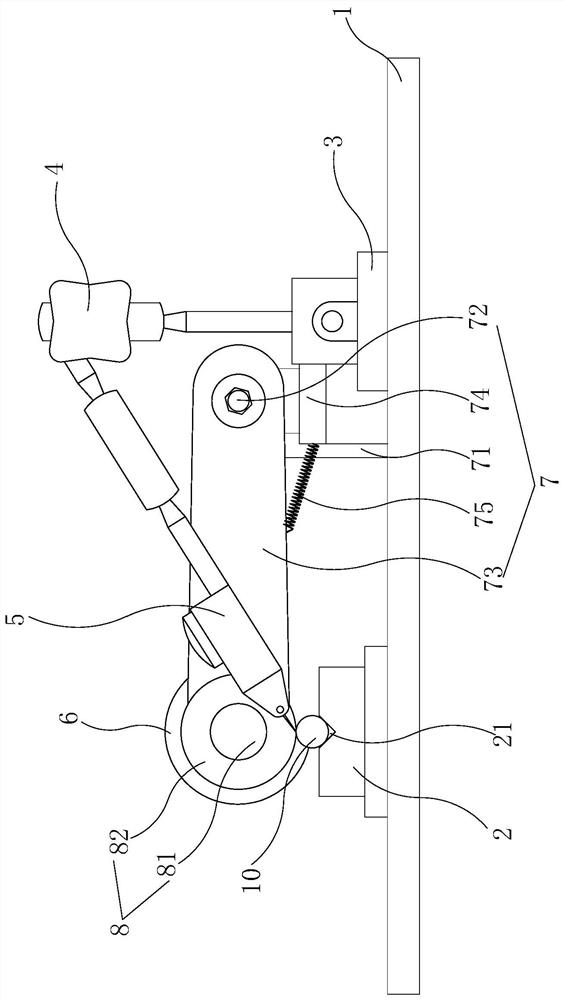
[0015] like Figure 1-Figure 3 As shown, the present invention is a kind of concentricity detection equipment, comprises machine platform 1, support frame 2, guide rail 3, dial gauge frame 4, dial gauge 5, motor 6, motor frame 7, guide wheel 8.

[0016] The support frame 2 and the guide rail 3 are all installed on the machine platform 1 and the support frame 2 is parallel to the guide rail 3, the dial indicator frame 4 can be moved and fixed on the guide rail 3, and one end of the dial indicator 5 is fixed on the dial indicator The free end of submeter frame 4, the other end of dial gauge 5 stretches to material rack 2, and the top surface of material rack 2 is provided with product placement 21, and this product placement position 21 is a V-shaped groove. The bottom of described motor frame 7 is installed on the machine platform 1, and motor 6 is fixedly installed on the free end of motor frame 7, and the output shaft of motor 6 is installed with the guide wheel 8 that is use...


PUM


Abstract

The invention discloses concentricity detection equipment which comprises a machine table, a material supporting frame, a guide rail, a dial indicator frame, a dial indicator, a motor, a motor frame and a guide wheel. The material supporting frame and the guide rail are both installed on the machine table, the material supporting frame is parallel to the guide rail, the dial indicator frame can move on the guide rail and be fixed, one end of the dial indicator is fixed to the free end of the dial indicator frame, the other end of the dial indicator extends to the material supporting frame, and a product containing position is arranged on the top face of the material supporting frame. The bottom of the motor frame is installed on the machine table, the motor is fixedly installed at the free end of the motor frame, a guide wheel used for driving products to rotate is installed on an output shaft of the motor, and the guide wheel is located at one end of the material supporting frame and located above the material supporting frame. As the rotation of the product is provided by the motor driving the guide wheel, the product rotates stably, the operation is simple, and the detection precision is high.

Description

technical field [0001] The invention relates to a detection device, in particular to a concentricity detection device. Background technique [0002] The ceramic ferrule is a small ceramic cylindrical tube fired with zirconia. It has a hard texture, a white and delicate color, and its finished product precision reaches sub-micron level. It is the most commonly used and the largest number of precision positioning parts in optical fiber communication networks. Used in the manufacture of fiber optic connectors, optical coupling of devices, etc. During the processing of the ceramic ferrule, it is necessary to measure the inner diameter and concentricity of the ceramic ferrule. The traditional coaxiality detector needs to manually place the workpiece on the workpiece support during measurement, and then adjust the three-dimensional translation stage to make the lens coaxial with the inner hole of the workpiece. During each measurement process, it is necessary to manually place th...

Claims


Application Information

Patent Timeline
IPC IPC(8): G01B5/252G01B5/00
CPCG01B5/252G01B5/0004
Inventor 罗仁峰邱金昌王铸泽郑雅萍
Owner 厦门新瓷材料科技有限公司
Why Eureka
Try Eureka