Rotating type belt taking-up and paying-off mechanism

A belt retractable and rotating technology, which is applied in the directions of winding strips, thin material handling, transportation and packaging, etc., can solve the problems of unbalanced force on the turret, and achieve the effects of stable rotation, reasonable layout, and low cost

Active Publication Date: 2014-11-26
XUZHOU WUYANG TECH
View PDF12 Cites 0 Cited by
  • Summary
  • Abstract
  • Description
  • Claims
  • Application Information

AI Technical Summary

Problems solved by technology

[0006] Aiming at the deficiencies of the prior art, a rotary retractable belt mechanism is now provided, which overcomes the defect of unbalanced force on the turret during the

Method used


Image

  • Rotating type belt taking-up and paying-off mechanism
  • Rotating type belt taking-up and paying-off mechanism
  • Rotating type belt taking-up and paying-off mechanism

Examples


Embodiment 1

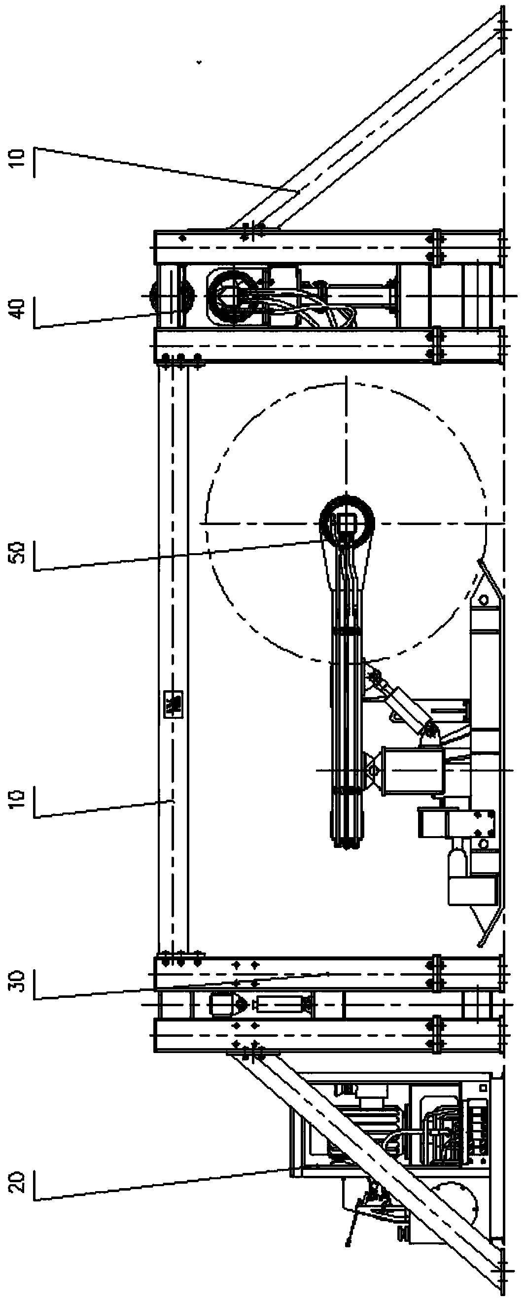
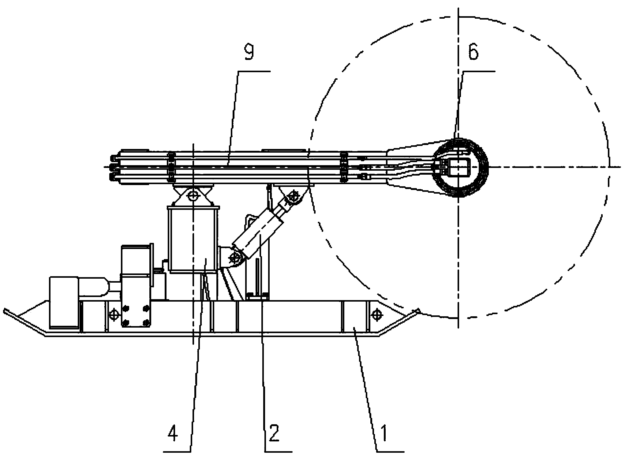
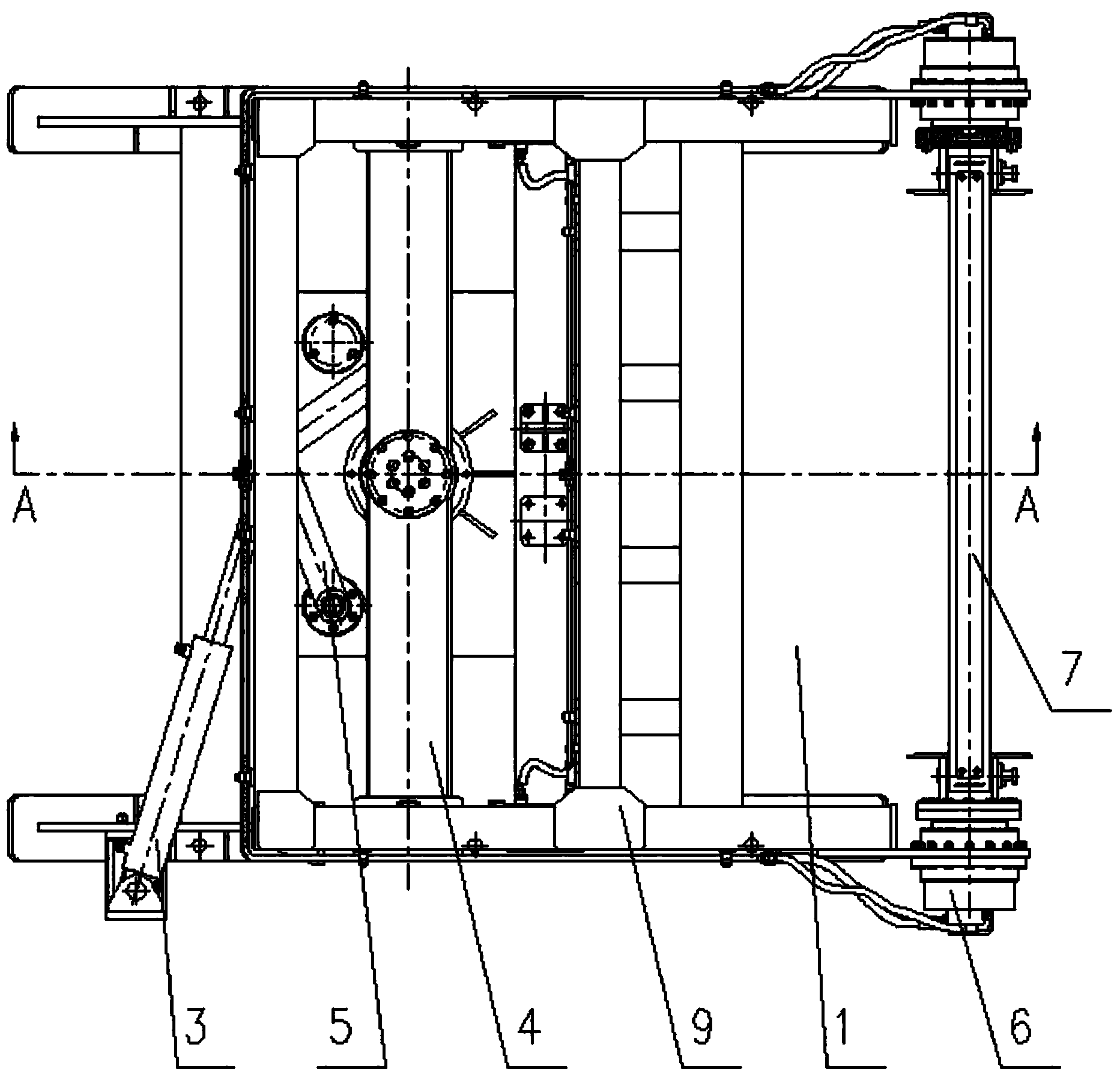
[0030] like Figure 2 to Figure 4 As shown, a rotary retractable belt mechanism includes a base 1, a turret 4 and a cantilever 9, the base 1 is provided with a vertical shaft 1.1, the turret 4 is set on the vertical shaft 1.1 and is connected with the vertical shaft 1.1 through a bearing, the cantilever 9 The bottom has three hinge points, one of which is hinged with the top of the turret 4 through a pin shaft, and the other two hinge points are hinged with the sides of the turret 4 through two lifting hydraulic cylinders 2, and the head of the cantilever 9 is connected There is a detachable take-up mandrel 7, the take-up mandrel 7 is driven to rotate by a hydraulic motor 6 located on its side, the tail of the base 1 is provided with a rotating hydraulic cylinder 3, and the lower side of the turret 4 is connected with a link mechanism 5, which is connected to The rod mechanism 5 is composed of two connecting rods, the two connecting rods are jointly hinged with the piston rod ...

Embodiment 2

[0038] like Figures 5 to 7 As shown, the second embodiment is basically the same as the first embodiment, except that an anti-roll deflection guide device 8 is provided on the inner side of the cantilever 9 .

[0039] When the hydraulic motor 6 drives the take-up mandrel 7 to start take-up, the anti-roll deflection guide device 8 starts to work, and the linear speeds of the guides at different positions and the take-up at different positions cooperate with each other, so that both ends of the rolled-out belt roll are neat And tight inside.

[0040] The anti-roll deflection guide device 8 can adopt two structural forms, wherein one anti-roll deflection guide device 8 includes a guide shaft connected to the inside of the cantilever 9 and several bearings sleeved outside the guide shaft and connected in series.

[0041] Another anti-roll deflection guide device 8 includes a guide shaft connected to the inside of the cantilever 9 and several nylon sleeves connected in series out...


PUM


Abstract

The invention relates to a belt taking-up and paying-off mechanism, in particular to a rotating type belt taking-up and paying-off mechanism for a telescopic belt conveyor. The rotating type belt taking-up and paying-off mechanism comprises a base (1), a rotating frame (4) and a cantilever (9). A stand shaft (1.1) is arranged on the base (1). The rotating frame (4) is arranged on the stand shaft (1.1) in a sleeved mode and is connected to the stand shaft (1.1) through a bearing. A detachable belt coiling mandrel (7) is arranged at the head portion of the cantilever. The belt coiling mandrel is driven by a hydraulic motor (6) arranged on the side face of the belt coiling mandrel to rotate. A rotating hydraulic cylinder (3) is arranged at the tail of the base. A link mechanism (5) is connected with the lower side of the rotating frame. The link mechanism comprises two connecting rods which are hinged to a piston rod head of the rotating hydraulic cylinder. One end of one connecting rod is connected with the side wall below a rotating frame mechanism. The other connecting rod is hinged to the base. A cylinder head of the rotating hydraulic cylinder is hinged to the side face of the base. The rotating frame of the belt taking-up and paying-off mechanism is even in stress during a rotating process, rotating is stable, and the service life of a hydraulic belt coiler is improved.

Description

technical field [0001] The invention relates to a retractable belt mechanism, in particular to a rotary retractable belt mechanism for a retractable belt conveyor. Background technique [0002] The hydraulic belt reel device is one of the standard supporting parts of the retractable belt conveyor. Its function is to quickly and quickly wind the full conveyor belt in the storage bin to the reel of the belt reel device, and then through the belt reel device. Rotate horizontally to move the coiled conveyor belt out of the frame, and then use the auxiliary transport tool to transport the conveyor belt away. [0003] Existing hydraulic belt winding devices such as figure 1 As shown, it is mainly composed of components such as frame 10, hydraulic pump station 20, fixed entrainment mechanism 30, pumping belt mechanism 40 and rotary retractable belt mechanism 50. The rotary take-up and take-up mechanism is used to take up the belt and transfer the conveyor belt to the outside of t...

Claims


Application Information

Patent Timeline
IPC IPC(8): B65H19/30B65H19/26B65H19/29
Inventor 侯友夫
Owner XUZHOU WUYANG TECH
Why Eureka
Try Eureka