Camera device and zoom lens
The technology of a zoom lens and a camera device, which is applied in the field of photography, can solve the problems of reducing the scope of application of the camera device, inconvenient use of the camera device, and the increase in the volume of the camera device, so as to reduce the number of cemented lenses, increase reliability, and reduce the number. Effect
- Summary
- Abstract
- Description
- Claims
- Application Information
AI Technical Summary
Problems solved by technology
Method used
Image
Examples
Embodiment 1
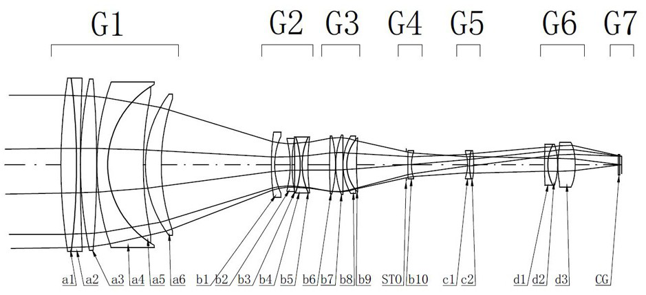
[0091] Such as figure 1 as shown, figure 1 It is a structural schematic diagram of an imaging device.
[0092] An imaging device, comprising: a zoom lens and an image pickup element configured to receive an image formed by the zoom lens; the image pickup element is a CCD or CMOS, and the image pickup element can be arranged on the image side IMG of the zoom optical lens.
[0093] The zoom lens is composed of six lens groups.
[0094] The zoom lens includes sequentially from the object plane side to the image plane side:
[0095] Fixed lens group G1 with positive refractive power, first zoom lens group G2 with negative refractive power, second zoom lens group G3 with positive refractive power, stop STO, third zoom lens group G4 with negative refractive power , anti-shake lens group G5 with negative refractive power, and focusing lens group G6 with positive refractive power.
[0096] The fixed lens group G1 sequentially includes from the object plane side to the image plane ...
Embodiment 2
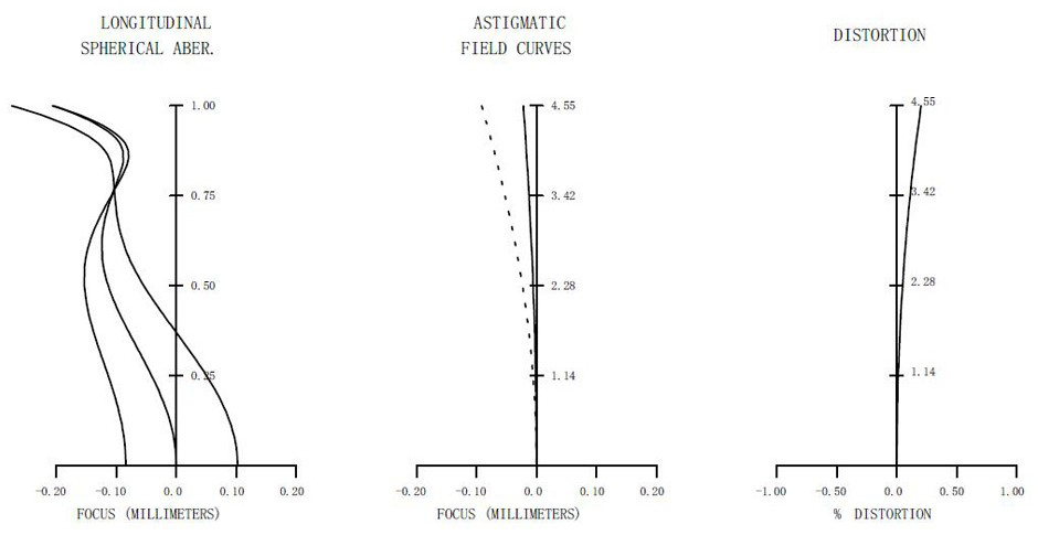
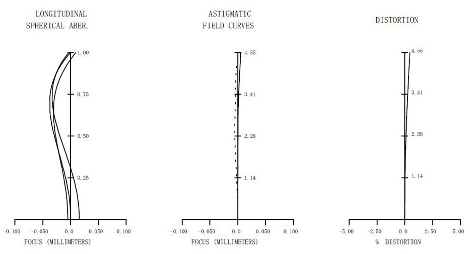
[0144] Such as Figure 1 to Figure 4 as shown, figure 1 It is a structural schematic diagram of a camera device, figure 2 It is the various aberration diagrams of the telephoto state of an imaging device described in this embodiment, image 3 It is the various aberration diagrams of the intermediate state of an imaging device described in this embodiment, Figure 4 It is the various aberration diagrams of a wide-angle state of an imaging device described in this embodiment; wherein, Figure 2 to Figure 4 The accompanying drawing on the left is a spherical aberration diagram of an imaging device described in this embodiment, Figure 2 to Figure 4 The figure in the middle is a field curvature diagram of an imaging device described in this embodiment, Figure 2 to Figure 4 The figure on the right in the figure is a distortion diagram of an imaging device described in this embodiment.
[0145] Such as figure 1 Shown, a kind of imaging device comprises: zoom lens and image p...
Embodiment 3
[0188] Such as Figure 5 to Figure 8 as shown, Figure 5 It is a structural schematic diagram of another camera device, Image 6 It is the various aberration diagrams in the telephoto state of another camera device described in this embodiment, Figure 7 It is the various aberration diagrams of the intermediate state of another imaging device described in this embodiment, Figure 8 It is the various aberration diagrams of the wide-angle state of another camera device described in this embodiment; wherein, Figure 6 to Figure 8 The accompanying drawing on the left is the spherical aberration diagram of another camera device described in this embodiment, Figure 6 to Figure 8 The figure in the middle is the field curvature diagram of another camera device described in this embodiment, Figure 6 to Figure 8 The figure on the right in the figure is a distortion diagram of another camera device described in this embodiment.
[0189] Such as Figure 5 Shown, a kind of imaging de...
PUM
 Abstract
Description
Claims
Application Information
 - R&D Engineer
- R&D Manager
- IP Professional
- Industry Leading Data Capabilities
- Powerful AI technology
- Patent DNA Extraction
Browse by: Latest US Patents, China's latest patents, Technical Efficacy Thesaurus, Application Domain, Technology Topic, Popular Technical Reports.
© 2024 PatSnap. All rights reserved.Legal|Privacy policy|Modern Slavery Act Transparency Statement|Sitemap|About US| Contact US: help@patsnap.com


