Control method for suppressing commutation failure based on hybrid cascade direct current power transmission system

A DC transmission system, commutation failure technology, applied in AC network circuits, AC network voltage adjustment, circuit devices, etc., can solve the voltage fluctuation of the sending end or receiving end grid, shorten the DC commutation failure time, reduce the frequency of the receiving end grid Fluctuation and other problems, to shorten the time, reduce the drop range, increase the effect of reactive power output

Pending Publication Date: 2022-03-08
JIANGSU ELECTRIC POWER CO
View PDF0 Cites 2 Cited by
  • Summary
  • Abstract
  • Description
  • Claims
  • Application Information

AI Technical Summary

Problems solved by technology

However, the conventional line commutation converter (LCC) composed of thyristors needs power support on the inverter side, which has the following defects: commutation failure is prone to occur when the AC voltage on the inverter side drops or the harmonic content increases: if the receiving end Multiple DC commutation failures in the grid at the same time will cause large fluctuations in the frequency of the grid at the receiving end; in addition, the LCC also consumes a large amount of reactive power during operation, which may easily lead to failures at the sending or receiving end when the DC operating conditions change or DC is blocked. Large fluctuations in terminal grid voltage
[0004] However, in the prior art, there is a lack of a control method based on hybrid cascaded DC transmission system to suppress commutation failure, so as to reduce the risk of DC commutation failure and shorten the time of DC commutation failure

Method used


Image

  • Control method for suppressing commutation failure based on hybrid cascade direct current power transmission system
  • Control method for suppressing commutation failure based on hybrid cascade direct current power transmission system
  • Control method for suppressing commutation failure based on hybrid cascade direct current power transmission system

Examples


Embodiment Construction

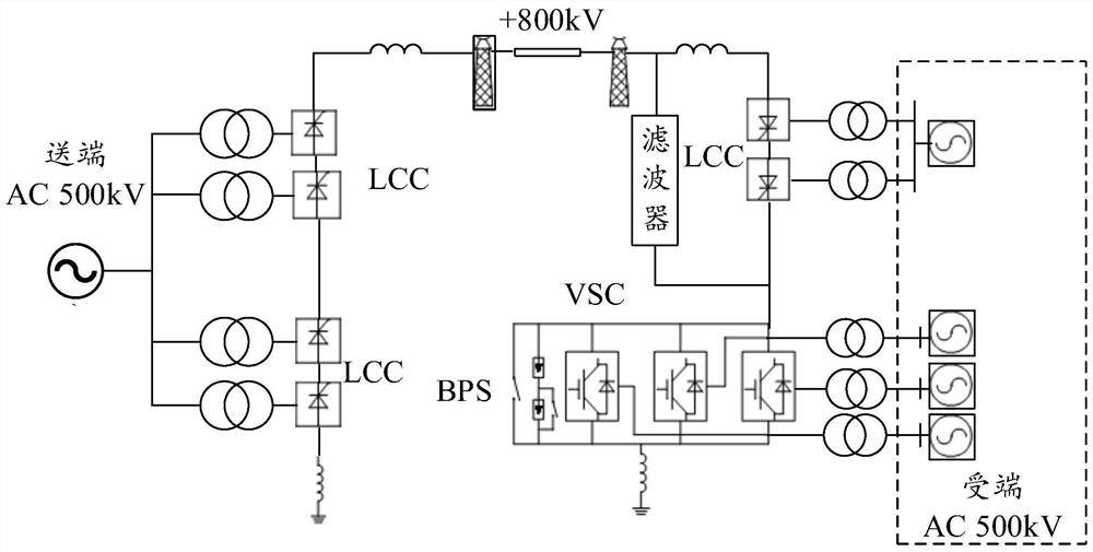
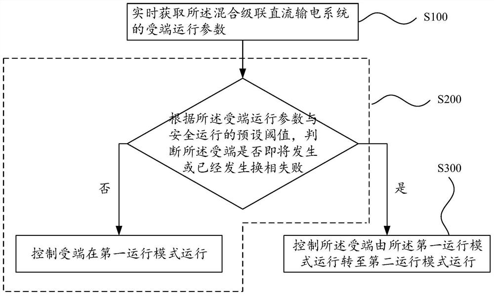
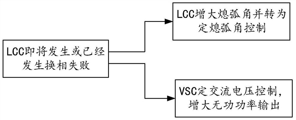
[0042]In order to make the purpose, advantages and features of the present invention clearer, the control method for suppressing commutation failure based on the hybrid cascaded direct current transmission system proposed by the present invention will be further described in detail below in conjunction with the accompanying drawings. It should be noted that all the drawings are in a very simplified form and use imprecise scales, and are only used to facilitate and clearly assist the purpose of illustrating the embodiments of the present invention. It should be understood that the drawings in the specification do not necessarily show the specific structure of the invention to scale, and that the illustrative features used to illustrate some principles of the invention in the drawings in the specification are also drawn in a somewhat simplified manner. The specific design features of the invention disclosed herein, including, for example, specific dimensions, orientations, locati...


PUM


Abstract

The invention provides a control method for suppressing commutation failure based on a hybrid cascade direct current power transmission system. The invention discloses a topological structure of a hybrid cascade direct current transmission system. The topological structure comprises a sending end adopting an LCC, a receiving end VSC converter or an LCC series VSC structure; the control method comprises the following steps: acquiring receiving end operation parameters of the hybrid cascade direct-current power transmission system in real time; according to the operation parameters of the receiving end and a preset threshold value of safe operation, judging whether the receiving end is about to generate or has generated commutation failure: if not, controlling the receiving end to operate in a first operation mode; and if yes, controlling the receiving end to switch from the first operation mode to a second operation mode. According to the control method for suppressing the commutation failure based on the hybrid cascade direct-current power transmission system, the commutation failure is suppressed, and meanwhile, the change of the transmission power of the direct-current system is reduced to the greatest extent.

Description

technical field [0001] The invention relates to the technical field of flexible direct current transmission, in particular to a control method for suppressing commutation failure based on a hybrid cascaded direct current transmission system. Background technique [0002] High-voltage / ultra-high-voltage DC transmission is one of the transmission methods widely used in my country's west-to-east power transmission. Due to the mature thyristor technology, it has great advantages in terms of capacity and cost compared with fully-controlled devices such as IGBTs. Therefore, these DC Inverters are basically composed of thyristors. However, the conventional line commutation converter (LCC) composed of thyristors needs power support on the inverter side, which has the following defects: commutation failure is prone to occur when the AC voltage on the inverter side drops or the harmonic content increases: if the receiving end Multiple DC commutation failures in the grid at the same ti...

Claims


Application Information

Patent Timeline
Patent Type & Authority Applications(China)
IPC IPC(8): H02J3/36H02J3/16
CPCH02J3/36H02J3/16H02J2003/365Y02E40/30Y02E60/60
Inventor 周挺吴金陵罗凯明张莉罗建裕刘书良李海峰李晓雯刘林罗安娜
Owner JIANGSU ELECTRIC POWER CO
Why Eureka
Try Eureka