Control method, device and equipment for suppressing commutation failure of HVDC (High Voltage Direct Current) system

A technology of commutation failure and control method, which is applied in the field of high-voltage direct current transmission, and can solve problems affecting the safe and stable operation of the power grid at the receiving end, commutation failure of the converter valve, etc.

Pending Publication Date: 2021-06-04
ELECTRIC POWER RESEARCH INSTITUTE, CHINA SOUTHERN POWER GRID CO LTD +1
View PDF1 Cites 0 Cited by
  • Summary
  • Abstract
  • Description
  • Claims
  • Application Information

AI Technical Summary

Problems solved by technology

[0004] Embodiments of the present invention provide a control method, device and equipment for suppressing commutation failure of an HVDC system, which are used to solve the problem of commutation failure of the converter valve when the AC system on the inverter side of the existing high-voltage direct current transmission system is disturbed. Technical Problems of Safe and Stable Operation of Receiving Power Grid

Method used


Image

  • Control method, device and equipment for suppressing commutation failure of HVDC (High Voltage Direct Current) system
  • Control method, device and equipment for suppressing commutation failure of HVDC (High Voltage Direct Current) system
  • Control method, device and equipment for suppressing commutation failure of HVDC (High Voltage Direct Current) system

Examples


Embodiment 1

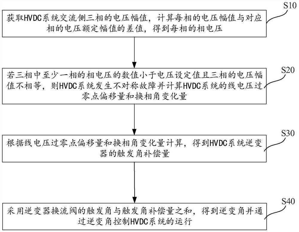
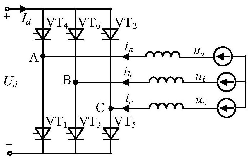
[0060] figure 1 It is a flow chart of the steps of the control method for suppressing the commutation failure of the HVDC system described in the embodiment of the present invention. figure 2 It is a schematic structural diagram of a converter valve of an HVDC system inverter in a control method for suppressing commutation failure of an HVDC system described in an embodiment of the present invention.

[0061] In the embodiment of the present invention, such as figure 2 As shown, the inverter valve of the HVDC system uses a six-pulse converter valve as a case for illustration. The converter valve of the high-voltage direct current transmission system (HVDC system) is usually composed of dozens of thyristor modules connected in series. In order for the thyristor to complete To turn off and restore the blocking ability, it is necessary to apply a reverse voltage at both ends of the thyristor until the free ions in the thyristor recombine with the gap and lose the conduction ab...

Embodiment 2

[0116] Figure 8 It is a frame diagram of a control device for suppressing commutation failure of an HVDC system described in an embodiment of the present invention.

[0117] like Figure 8 As shown, the embodiment of the present invention also provides a control device for suppressing HVDC system commutation failure, including a phase voltage acquisition module 10, a first calculation module 20, a second calculation module 30 and a control module 40;

[0118] A phase voltage acquisition module 10, configured to acquire the voltage amplitudes of the three phases on the AC side of the HVDC system, calculate the difference between the voltage amplitude of each phase and the rated voltage amplitude of the corresponding phase, and obtain the phase voltage of each phase;

[0119] The first calculation module 20 is used to calculate the HVDC system line voltage overvoltage according to the fact that the value of the phase voltage of at least one of the three phases is less than the...

Embodiment 3

[0134] An embodiment of the present invention provides a control device for suppressing commutation failure of an HVDC system, including the above-mentioned control device for suppressing commutation failure of an HVDC system.

[0135] It should be noted that the devices in the device in the third embodiment have been described in detail in the second embodiment, and the content of the device in the center of the device will not be described in detail in the third embodiment.


PUM


Abstract

The invention relates to a control method, device and equipment for suppressing commutation failure of an HVDC (high voltage direct current) system, and the method comprises the steps: obtaining the voltage amplitudes of three phases at the AC side of the HVDC system, calculating the difference between the voltage amplitude of each phase and the rated voltage amplitude of the corresponding phase, and obtaining the phase voltage of each phase; if the value of the phase voltage of at least one phase in the three phases is smaller than the voltage set value and the voltage amplitudes of the three phases are not equal, calculating the line voltage zero crossing offset and the commutation angle variation of the HVDC system; calculating according to the line voltage zero crossing offset and the commutation angle variation to obtain the trigger angle compensation amount of the inverter of the HVDC system; and obtaining an inversion angle by adopting the sum of the trigger angle of the converter valve of the inverter and the trigger angle compensation amount, and controlling the operation of the HVDC system through the inversion angle. The purpose of suppressing commutation failure is achieved by calculating the trigger angle compensation amount when a three-phase asymmetric fault occurs on the inversion alternating current side of the HVDC system and compensating the trigger angle compensation amount to a trigger angle of a converter valve of an inverter.

Description

technical field [0001] The invention relates to the technical field of high voltage direct current transmission, in particular to a control method, device and equipment for suppressing commutation failure of an HVDC system. Background technique [0002] In recent years, HVDC transmission projects have been used more and more in power grids. In HVDC transmission projects, power grid transmission is mainly realized through high voltage direct current (HVDC) systems. On the inverter side of HVDC transmission systems, AC When the system is disturbed, the commutation valve of the HVDC transmission system is prone to commutation failure, which seriously threatens the safe and stable operation of the receiving end power grid. However, the commutation failure of the converter valve in the HVDC transmission system is related to factors such as commutation voltage, DC current, commutation reactance, and firing angle. [0003] The converter valve of the HVDC power transmission system ...

Claims


Application Information

Patent Timeline
Patent Type & Authority Applications(China)
IPC IPC(8): H02J3/36
CPCH02J3/36Y02E60/60
Inventor 魏伟刘崇茹李欢单俊儒徐诗甜蒋思雯
Owner ELECTRIC POWER RESEARCH INSTITUTE, CHINA SOUTHERN POWER GRID CO LTD
Why Eureka
Try Eureka