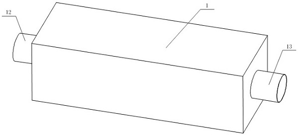
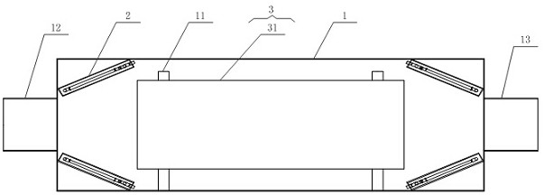
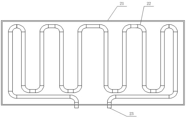
Airflow auxiliary heating device utilizing inclined plane in box body

A technology for auxiliary heating and heating devices, which is applied in the direction of air heaters, fluid heaters, lighting and heating equipment, etc. It can solve the problems of affecting the airflow temperature distribution, increasing the cost, reducing the gap between the pipe and the box section, etc., to achieve good The effect of airflow uniformity

Pending Publication Date: 2022-03-11
SHENZHEN KING TEAM PRECISION TECH
View PDF0 Cites 0 Cited by
  • Summary
  • Abstract
  • Description
  • Claims
  • Application Information

AI Technical Summary

Problems solved by technology

[0002] When the air flow enters the pipe or box with a larger diameter from a pipe with a smaller diameter, a vortex will be generated at the inner wall of the joint. Heat exchange, thereby affecting the temperature distribution of the entire airflow; the usual solution is to increase the diameter of the airflow inlet pipe to reduce the cross-sectional gap between the pipe and the box, thereby reducing the generation of vortices, or changing the shape of the two to make the box The internal airflow tends to be gentle; but these methods will increase the cost of design and production, and may affect the function of the box

Method used


Image

  • Airflow auxiliary heating device utilizing inclined plane in box body
  • Airflow auxiliary heating device utilizing inclined plane in box body
  • Airflow auxiliary heating device utilizing inclined plane in box body

Examples


Embodiment Construction

[0026] The following will clearly and completely describe the technical solutions in the embodiments of the present invention with reference to the accompanying drawings in the embodiments of the present invention. Obviously, the described embodiments are only some, not all, embodiments of the present invention. Based on the embodiments of the present invention, all other embodiments obtained by persons of ordinary skill in the art without making creative efforts belong to the protection scope of the present invention.

[0027] In the description of the present invention, it should be noted that the terms "center", "upper", "lower", "left", "right", "vertical", "horizontal", "inner", "outer" etc. The indicated orientation or positional relationship is based on the orientation or positional relationship shown in the drawings, and is only for the convenience of describing the present invention and simplifying the description, rather than indicating or implying that the referred d...


PUM


Abstract

The invention discloses an airflow auxiliary heating device utilizing an inclined plane in a box body. The airflow auxiliary heating device comprises a main body, an auxiliary heating device and a heating device, the auxiliary heating devices are distributed around the inner wall of the main body and are arranged in the middle in the main body; a plurality of fixing columns are arranged in the main body and are used for fixing the heating device; two ends of the main body are respectively provided with a first ventilating duct and a second ventilating duct; the first ventilation pipeline and the second ventilation pipeline are communicated with the interior of the main body; an included angle of 30-60 degrees is formed between the contact surface of the bottom plate and the main body and the main body, so that good airflow uniformity is achieved, and the auxiliary heating device can achieve a good auxiliary heating effect; after entering the main body from the first ventilation pipeline, gas is in contact with the auxiliary heating device to be heated, and the heated gas enters the heating device to be further heated and is discharged out of the main body through the second ventilation pipeline; the flow rates of gas in all positions in the main body tend to be similar, so that the whole heating environment becomes uniform, and a better heating effect is achieved.

Description

technical field [0001] The invention relates to the technical field of heating, in particular to an airflow auxiliary heating device using an inclined surface inside a box body. Background technique [0002] When the air flow enters the pipe or box with a larger diameter from a pipe with a smaller diameter, a vortex will be generated at the inner wall of the joint. Heat exchange, thereby affecting the temperature distribution of the entire airflow; the usual solution is to increase the diameter of the airflow inlet pipe to reduce the cross-sectional gap between the pipe and the box, thereby reducing the generation of vortices, or changing the shape of the two to make the box The internal airflow tends to be gentle; but these methods will increase the cost of design and production, and may affect the function of the box. [0003] The simulation results of the internal heating box with a pipe diameter of 10 cm and a box section of a side length of 30 cm show that if a right a...

Claims


Application Information

Patent Timeline
IPC IPC(8): F24H3/00F24H9/00F24H9/1863
CPCF24H3/002F24H9/0063F24H9/1863
Inventor 刘兴志傅益权姚英邦
Owner SHENZHEN KING TEAM PRECISION TECH
Why Eureka
Try Eureka