Stove combustor with temperature sensor

A technology of temperature sensor and burner, which is applied in the direction of burner, gas fuel burner, combustion method, etc., can solve the problems of affecting the output of the temperature measured by the temperature sensor, unreliable positioning, easy deformation, etc., and achieve better air mixing effect. Excellent, reasonable installation structure, good airflow uniformity

Inactive Publication Date: 2016-11-16
NINGBO FOTILE KITCHEN WARE CO LTD
View PDF7 Cites 0 Cited by
  • Summary
  • Abstract
  • Description
  • Claims
  • Application Information

AI Technical Summary

Problems solved by technology

The above-mentioned existing temperature sensors have a relatively simple installation structure with the gas stove, unreliable positioning, and are easy to deform and slide, resulting in direct contact between t

Method used


Image

  • Stove combustor with temperature sensor
  • Stove combustor with temperature sensor
  • Stove combustor with temperature sensor

Examples


Embodiment 1

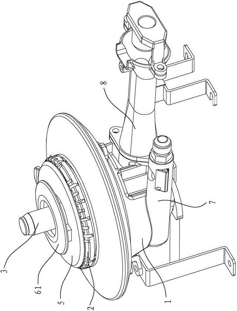
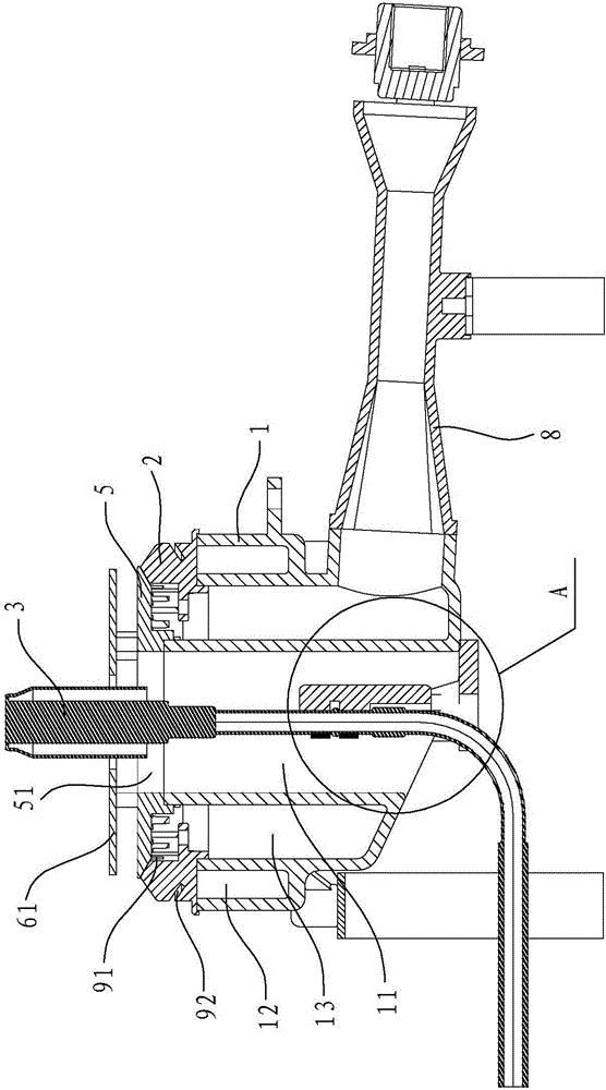
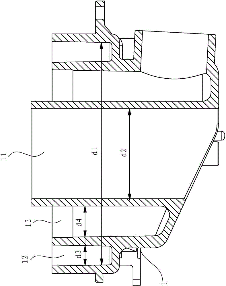
[0033] Such as Figure 1 to Figure 3 As shown, the cooker burner in this embodiment includes a base 1, a fire cover 2, a temperature sensor 3, a sensor bracket 4, a cover plate 5, a first heat shield 61, an outer ring gas injection pipe 7 and an inner ring gas injection pipe. Injection pipe 8 and other components, wherein the base 1 includes an outer ring cavity 12 and an inner ring cavity 13, the outer ring cavity 12 communicates with the outer ring gas injection tube 7, and the inner ring cavity 13 communicates with the inner ring cavity The gas injection pipes 8 are connected. The fire cover 2 is an annular fire cover, an upper ring fire channel 91 communicating with the inner ring cavity 13 is formed between the cover plate 5 and the fire cover 2, and the upper ring fire channel forms a large fire ring, and the inside of the fire cover 2 is formed to connect with the outer ring cavity. Body 12 communicates with the lower ring fire channel 92, and the lower ring fire chann...

Embodiment 2

[0047] Such as Figure 7 As shown, the cooker burner in this embodiment is equipped with an annular second heat-proof plate 62 on the upper end of the temperature sensor 3, the second heat-proof plate 62 can move synchronously with the temperature sensor 3, and the second heat-proof plate 62 is located above the cover plate 5 . The rest of the structure of the cooktop burner in this embodiment is the same as that in Embodiment 1, and will not be further described here.

Embodiment 3

[0049] Such as Figure 8 As shown, the cooker burner in this embodiment is not provided with a heat-resistant plate, and the rest of the structure is the same as that in Embodiment 1, and will not be described here.


PUM

PropertyMeasurementUnit
Diameteraaaaaaaaaa
Diameteraaaaaaaaaa
Diameteraaaaaaaaaa

Abstract

The invention discloses a stove combustor with a temperature sensor. The stove combustor comprises a base, a fire cover, the temperature sensor, an outer ring gas injection pipe and an inner ring gas injection pipe; the base is provided with an outer ring cavity and an inner ring cavity, the outer ring cavity is communicated with the outer ring gas injection pipe, the inner ring cavity is communicated with the inner ring gas injection pipe, and the stove combustor is characterized in that a mounting cavity is formed in the center of the inner ring cavity, an opening is formed in the position, located at the bottom of the base, of the mounting cavity, and the temperature sensor is mounted in the mounting cavity. Compared with the prior art, the stove combustor has the beneficial effects that the mounting cavity used for mounting of the temperature sensor is formed in the center of the inner ring cavity of the stove combustor, and can achieve the flow guide effect, the uniformity of the gas flow inside the base is better, the gas mixing effect is better, in addition, after the temperature sensor is mounted in the mounting cavity, the gas mixing effect is not affected, and a mounting structure is reasonable.

Description

technical field [0001] The invention relates to a burner, in particular to a cooker burner with a temperature sensor. Background technique [0002] Many existing cooker burners are equipped with temperature sensors on the base. The temperature sensor can detect the temperature of the bottom of the pot in real time. The controller in the cooker burner can control the cooker according to the data measured by the temperature sensor. In this way, the gas utilization efficiency can be effectively improved and the cooker can be precisely controlled to solve accidents such as overheating, sticky cooker, dry cooker burning and flameout. [0003] Existing stove burners are generally provided with two annular chambers on the base, which are respectively an inner annular chamber and an outer annular chamber, an inner ring fire cover is installed on the inner annular chamber, and The outer ring fire cover, when the burner is working, an inner ring fire and an outer ring fire are respec...

Claims


Application Information

Patent Timeline
IPC IPC(8): F24C3/12F23D14/62F23D14/72
CPCF24C3/126F23D14/62F23D14/72
Inventor 严力峰章建峰徐强陈迪龙郑军妹茅忠群诸永定
Owner NINGBO FOTILE KITCHEN WARE CO LTD
Why Eureka
Try Eureka