Illuminating device and imaging method for visual inspection of defects on outer surface of steel pipe

A lighting device and visual inspection technology, which is applied to measuring devices, material analysis through optical means, instruments, etc., can solve problems such as uneven lighting of steel pipes, and achieve the goal of preventing serious reflections, leak detection, and 360° uniform lighting imaging Effect

Pending Publication Date: 2022-03-11
ZHEJIANG JIULI HI TECH METALS
View PDF0 Cites 2 Cited by
  • Summary
  • Abstract
  • Description
  • Claims
  • Application Information

AI Technical Summary

Problems solved by technology

[0004] The purpose of the present invention is to overcome the defects in the above-mentioned prior art, and provide a barrel-shaped 360° uniform illumination, which can effectively solve the problems caused by the uneven illumination of the traditional light source on the steel pipe and the imaging of the oblique illumination, which is used for the defects of the outer surface of the steel pipe. Illumination device and imaging method for visual inspection

Method used


Image

  • Illuminating device and imaging method for visual inspection of defects on outer surface of steel pipe
  • Illuminating device and imaging method for visual inspection of defects on outer surface of steel pipe
  • Illuminating device and imaging method for visual inspection of defects on outer surface of steel pipe

Examples


Embodiment Construction

[0027] Embodiments of the present invention will be described in detail below in conjunction with the accompanying drawings.

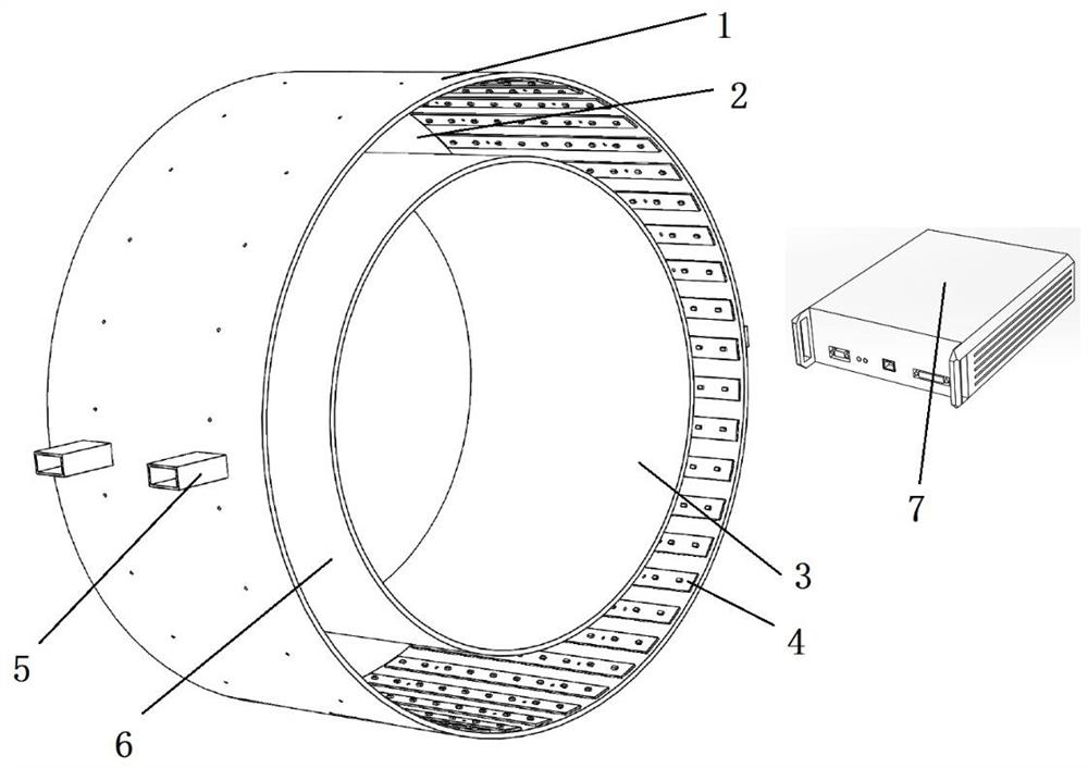
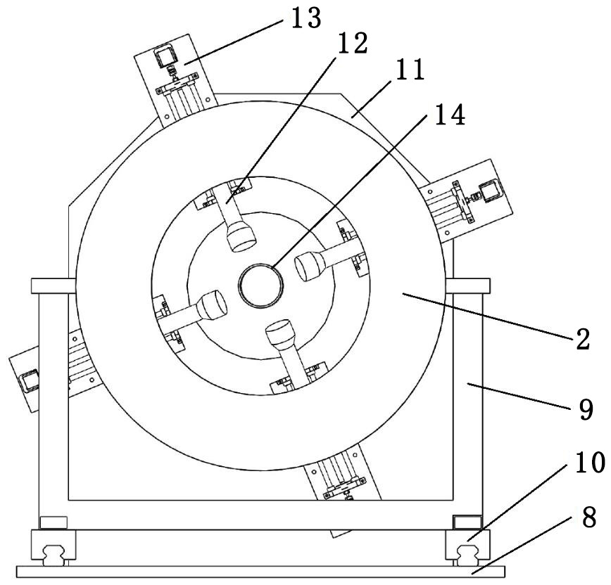
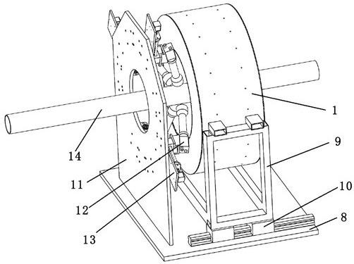
[0028] Such as Figure 1-3 As shown, a lighting device for visual detection of defects on the outer surface of steel pipes includes a lamp housing 1 and a lamp shade 3 arranged concentrically, the lamp housing 3 is located in the lamp housing 1, and a connecting The side plate 2, the side plate 2 is located on the opposite sides of the lamp housing 1 and the lampshade 3; the inner wall of the lamp housing 1 is provided with a plurality of circumferentially arranged LED light strips 4, and the LED light strips 4 are arranged facing the lampshade 3; the lampshade 3 It is made of transparent material, and the outer surface of the lampshade 3 is attached with a uniform light film 6; the lamp housing 1 is provided with a drive controller 7 electrically connected to the LED light bar 4, and the drive controller 7 synchronously controls all the LED light bars...


PUM

PropertyMeasurementUnit
diameteraaaaaaaaaa

Abstract

A lighting device for visual inspection of defects on the outer surface of a steel pipe comprises a lamp shell and a lampshade which are concentrically arranged, the lampshade is located in the lamp shell, connected side plates are arranged between the lamp shell and the lampshade, and the side plates are located on the two opposite sides of the lamp shell and the lampshade; a plurality of circumferentially arranged LED lamp strips are arranged on the inner wall of the lamp shell, and the LED lamp strips are arranged towards the lampshade; the lampshade is made of transparent materials, and a light uniformizing film is attached to the outer surface of the lampshade. A driving controller electrically connected with the LED lamp strips is arranged outside the lamp shell, and the driving controller synchronously controls all the LED lamp strips. Opposite lamp shell brackets are arranged on the outer wall of the lamp shell; compared with the prior art, when the camera obliquely faces the inner side of the barrel lamp, the object space corresponding to the imaging surface of the camera sensor is the inner wall, uniformly emitting light, of the barrel lamp, so that stray light generated by reflection cannot be introduced, and the pixel difference on the plane of the sensor is only caused by different surface shapes and roughness of the surface of a steel pipe; therefore, 360-degree uniform illumination imaging on the surface of the high-reflection steel pipe can be realized.

Description

technical field [0001] The invention relates to the technical field of visual defect detection thereof, in particular to an illumination device and an imaging method for visual detection of defects on the outer surface of steel pipes. Background technique [0002] The visual detection of surface defects of steel pipes is an indispensable process before the steel pipes leave the factory. With the rapid development of machine vision in recent years and its popularization and application in the industrial field, the visual detection of surface defects of steel pipes has also begun to change from manual to computer automatic. Recognize the direction change. The automatic recognition of steel pipe outer surface defects can be mainly divided into two methods according to different sensors, one is three-dimensional surface recognition based on line-scanning laser sensors, and the other is two-dimensional image recognition based on industrial cameras. The former usually comes with ...

Claims


Application Information

Patent Timeline
Patent Type & Authority Applications(China)
IPC IPC(8): G01N21/952G01N21/01
CPCG01N21/952G01N21/01G01N2021/0112
Inventor 简慧杰杨康吴侃孙明浩叶超李泰栋李欢妮高建荣王宝顺苏诚
Owner ZHEJIANG JIULI HI TECH METALS
Why Eureka
Try Eureka