Electromagnetic damping type transmission conductor galloping suppression device

A technology of electromagnetic damping and power transmission wires, which is applied in the direction of mechanical vibration attenuation devices, devices for maintaining the distance between parallel conductors, installation of cables, etc., can solve problems such as lines that cannot be effectively solved or suppressed, galloping, etc. Improving the effect of suppressing effects

Pending Publication Date: 2022-03-11
CHINA ELECTRIC POWER RES INST
View PDF0 Cites 0 Cited by
  • Summary
  • Abstract
  • Description
  • Claims
  • Application Information

AI Technical Summary

Problems solved by technology

[0005] In order to solve the problem that the existing technology cannot effectively solve or suppress the galloping of the line, the present invention proposes an el...

Method used


Image

  • Electromagnetic damping type transmission conductor galloping suppression device
  • Electromagnetic damping type transmission conductor galloping suppression device
  • Electromagnetic damping type transmission conductor galloping suppression device

Examples


Embodiment 1

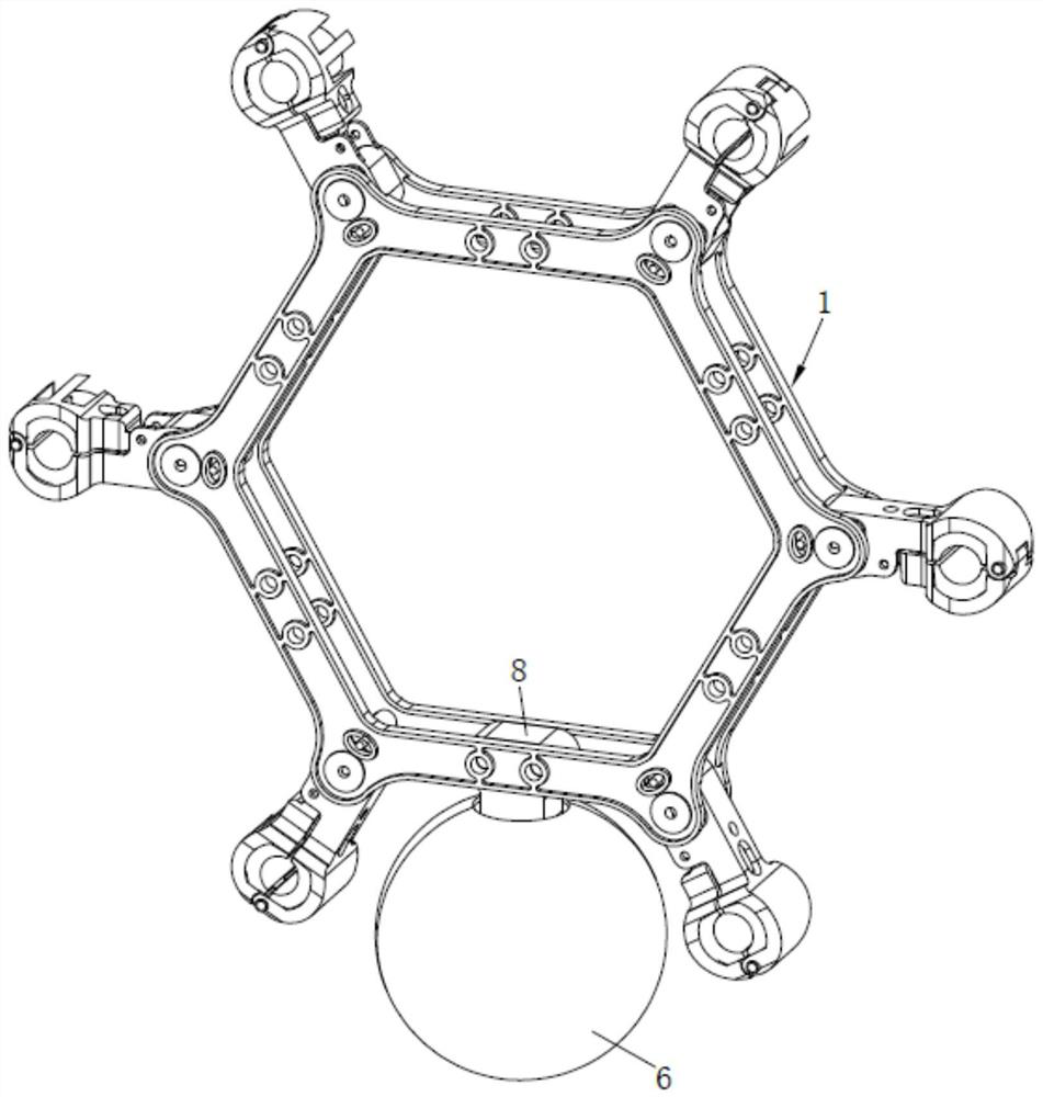
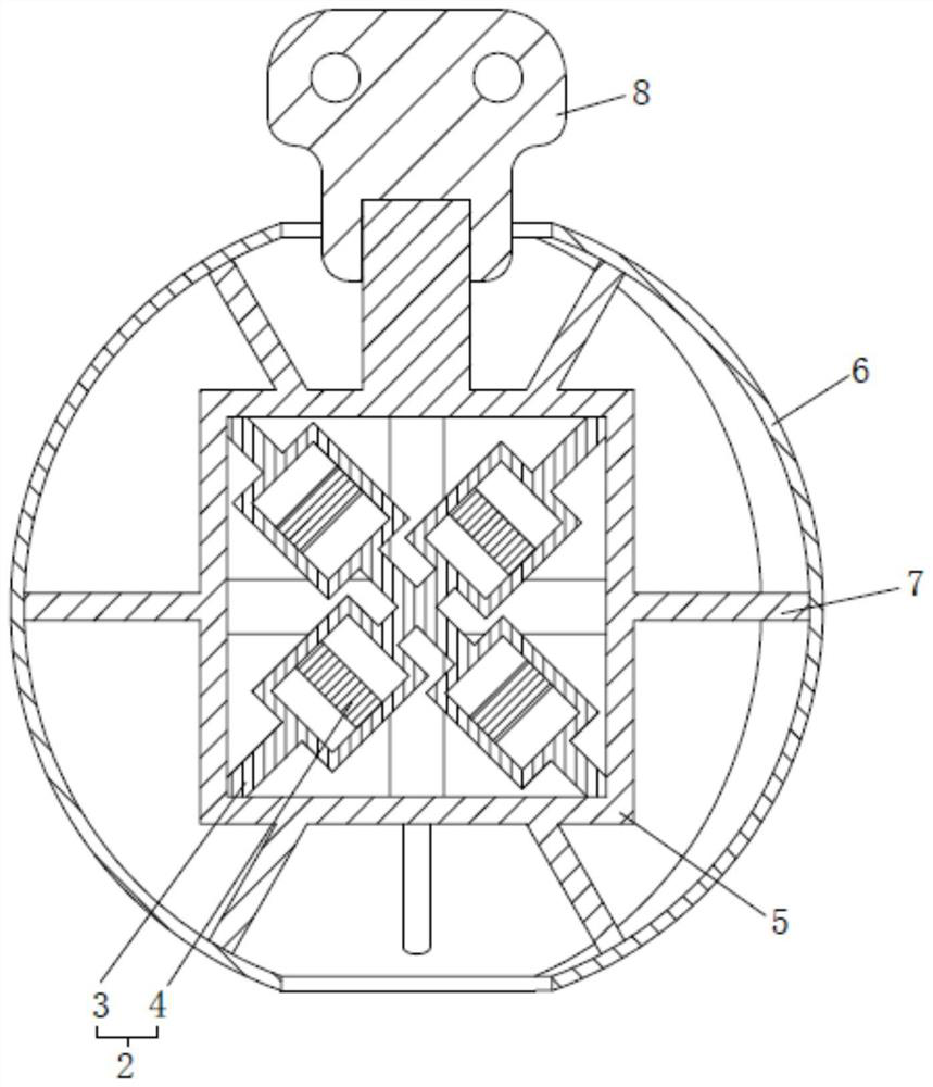
[0045] An electromagnetic damping type transmission wire galloping suppression device, such as figure 1 and image 3 As shown, it includes a wire spacer 1 and an electromagnetic damping device 2 for suppressing wire galloping; the electromagnetic damping device 2 includes two cross-connected metal tubes 3; each metal tube 3 is provided with two accommodating cavities , and the two accommodating cavities on each metal tube 3 are respectively arranged on both sides of the crossing fixing position of the two metal tubes 3; the two metal tubes 3 are relatively fixed inside or below the wire spacer 1. The electromagnetic damping device 2 also includes four permanent magnets 4 that are relatively free to move in the housing cavity. In this embodiment, the permanent magnet 4 is made of permanent NdFeB strong magnets, and the connection methods between the metal tube 3 and the housing cavity include but not limited to welding and integral molding. In this actual strength, the metal t...

Embodiment 2

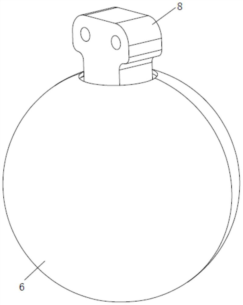
[0092] Electromagnetic damping device 2 can also be two connecting rods 8 among the present invention, as Figure 5 , Figure 6 and Figure 7 As shown; the side of the installation housing 5 facing the connecting rod 8 is perpendicular to the axial direction of the connecting rod, the lower end of one of the connecting rods 8 is installed on the upper end of the installation housing 5, and the upper end is installed on the upper end of the two regular hexagonal ring plates between the two regular hexagonal ring plates through bolts; the upper end of the other connecting rod 8 is installed on the lower end of the installation shell 5, and the lower end is installed between the lower ends of the two regular hexagonal ring plates, and passed through The bolts are tightly connected with two regular hexagonal ring plates.


PUM


Abstract

An electromagnetic damping type transmission conductor galloping suppression device comprises a conductor spacer and an electromagnetic damping device used for suppressing conductor galloping. The electromagnetic damping device comprises two metal pipes which are fixedly connected in a crossed mode. Each metal pipe is provided with two containing cavities, and the two containing cavities in each metal pipe are formed in the two sides of the crossed and fixedly-connected position of the two metal pipes correspondingly. The two metal tubes are oppositely fixed on the inner side or below the conductor spacer; the electromagnetic damping device further comprises four permanent magnets which are arranged in the containing cavity in a sleeved mode and can move relatively and freely. According to the device, induced eddy current is generated through relative movement between the permanent magnet and the metal pipe and reacts on the magnetic pole, and the purposes of widening the vibration absorption frequency range and improving the suppression effect are achieved.

Description

technical field [0001] The invention relates to the technical field of power grid disaster prevention, in particular to an electromagnetic damping type transmission wire galloping suppression device. Background technique [0002] my country is one of the countries with the most serious ice-coated galloping of overhead transmission lines. Galloping accidents have shown the characteristics of higher frequency of occurrence, wider range of influence, and increased losses in recent years, which seriously threatens the safe and stable operation of the power grid. Especially with the rapid development of my country's power grid construction, coupled with my country's special meteorological and geographical conditions, line galloping accidents have increased significantly, and the hazards have also become more and more serious. Domestic transmission line galloping research started late. In recent years, galloping accidents in my country have become more frequent and the disasters c...

Claims


Application Information

Patent Timeline
IPC IPC(8): H02G7/14H02G7/12
CPCH02G7/125
Inventor 司佳钧刘胜春刘龙周立宪王景朝刘鹏刘彬齐翼赵彬展雪萍李冬青顾建张暕
Owner CHINA ELECTRIC POWER RES INST
Why Eureka
Try Eureka