Expansion type self-locking anchor

An inflatable, anchoring technology, applied in the field of medical devices, can solve problems such as steel plate detachment from bone surface, muscle group damage, and long path.

Pending Publication Date: 2022-03-15
EAGLESCOPE MEDICAL TECH CO LTD
View PDF0 Cites 1 Cited by
  • Summary
  • Abstract
  • Description
  • Claims
  • Application Information

AI Technical Summary

Problems solved by technology

In the prior art, by cutting the skin at the projection of the acromioclavicular joint, mobilizing the acromion and the clavicle, a channel is established in the acromion of the clavicle and the scapula to enter the acromioclavicular joint, a plastic ligament is conducted in the channel and passed through a cable tie and The wounds are sutured layer by layer to connect the ends, that is, channels need to be opened on both sides below the scapula and above the clavicle. Specifically, due to the large volume of the square-shaped acromioclavicular plate, and the small inner diameter of the channel above the clavicle, it is impossible to open a channel above the clavicle. The approach, therefore, can only pre-enter the square-shaped acromioclavicular plate from the channel below the scapula until the acromioclavicular plate touches the scapula, and then use a special lead tool to pass through the scapula from the access channel above the clavicle to place the acromioclavicular plate on the The plastic ligament of the scapula passes through the hole of the clavicle from the lower side of the scapula to its outer surface and is fixed on the outer surface of the acromion of the clavicle by knotting or fixed on the outer surface of the acromion by a steel plate. The muscle group in this area is damaged, and the patient's shoulder is under pressure during the period of incomplete recovery, and the steel plate will detach from the bone surface.

Method used


Image

  • Expansion type self-locking anchor
  • Expansion type self-locking anchor
  • Expansion type self-locking anchor

Examples


Embodiment Construction

[0022] The present invention is further illustrated below with reference to the accompanying drawings and the examples given, but are not limited thereto.

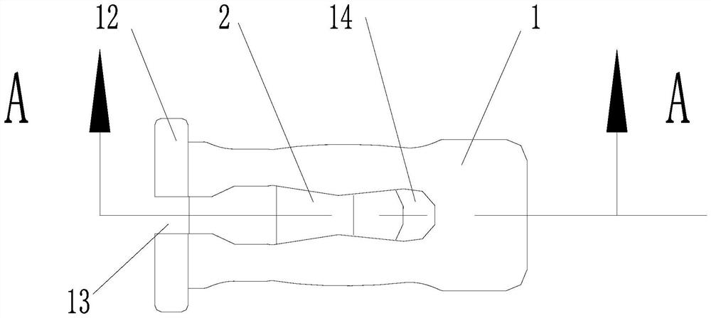
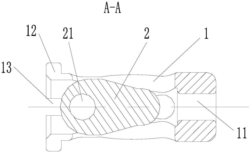
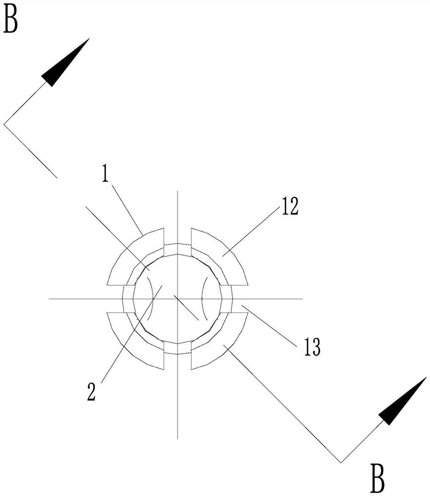
[0023] Such as figure 1 , 2 , 3, 4, 5, 6, 7, 8, and 9, an expanded self-locking anchor, including an integral anchor body 1 and an anchor head 2, the anchor head 2 penetrating into an anchor body In the inner cavity of the anchor body 1, one end of the anchor body 1 is provided with a wire hole 11, and the other end is provided with an anchor head lock 12, and an outer diameter of one end diameter of the anchor body 1 is larger than the outer diameter of the other end, the anchor head The lock 12 is provided with a plurality of elastic shrink portions 13 in the circumferential direction, and the peripheral wall of the anchor body 1 is provided with a threaded transition hole 14 in the axial direction thereof, and each elastic shrink port 13 is A threaded transition hole 14 is connected, and one end of the anchor head 2 is prov...


PUM


Abstract

The expansion type self-locking anchor is characterized in that the expansion type self-locking anchor comprises an anchor body and an anchor head which are integrally columnar, the anchor head penetrates into an inner cavity of the anchor body, a threading hole is formed in one end of the anchor body, an anchor head locking edge is arranged at the other end of the anchor body, and the outer diameter of one end of the anchor body is larger than that of the other end of the anchor body; a plurality of elastic contraction openings are formed in the anchor head locking edge in the circumferential direction of the anchor head locking edge, threading transition holes are formed in the circumferential wall of the anchor main body in the axial direction of the anchor main body, each elastic contraction opening is communicated with one threading transition hole, and a threading fixing hole is formed in one end of the anchor head. An approach channel can be established from one side of the clavicle, the path is shortened, and damage to muscles and groups below the scapula can be avoided.

Description

Technical field [0001] The present invention relates to an anchor, which specifically involves an expansion self-locking anchor, belonging to the technical field of medical devices. Background technique [0002] If the shoulder lock joint dislocation is accompanied by ligament misalignment, the situation of breakage occurs, it needs to be repaired, because the ligament is related to the contraction of muscles, dislocation, after breaking, there will be pain, activity is limited. It has been technically cut through the skin, active shoulder and clavicle in the projection of the shoulder lock, and the channel is created in the shoulder lock joint in the shoulder of the clavicle and the shoulders of the shoulder, and a plastic ligament is conducted in the channel and passes through the tie. The tape-by-layer wound is sutured, that is, it is necessary to open the channel at both sides of the shoulder blade and the upper side of the clavicle. Specifically, due to the size of the shoul...

Claims


Application Information

Patent Timeline
Patent Type & Authority Applications(China)
IPC IPC(8): A61B17/064A61B17/04A61B17/80
CPCA61B17/0642A61B17/0401A61B17/8052A61B17/8061A61B2017/0408
Inventor 房志刚贺军陈建良李想花金锦
Owner EAGLESCOPE MEDICAL TECH CO LTD
Why Eureka
Try Eureka