Electromechanical machining equipment with automatic clamping and automatic cutting stopping functions
A technology for automatic clamping and processing equipment, applied in metal processing equipment, metal processing machinery parts, clamping, etc., can solve problems such as inconvenient use, automatic cutting and stopping, increased workload of staff, etc., to achieve improvement Item quality, effect of reducing workload
- Summary
- Abstract
- Description
- Claims
- Application Information
AI Technical Summary
Problems solved by technology
Method used
Image
Examples
Embodiment 1
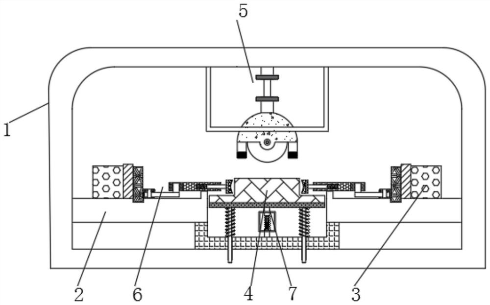
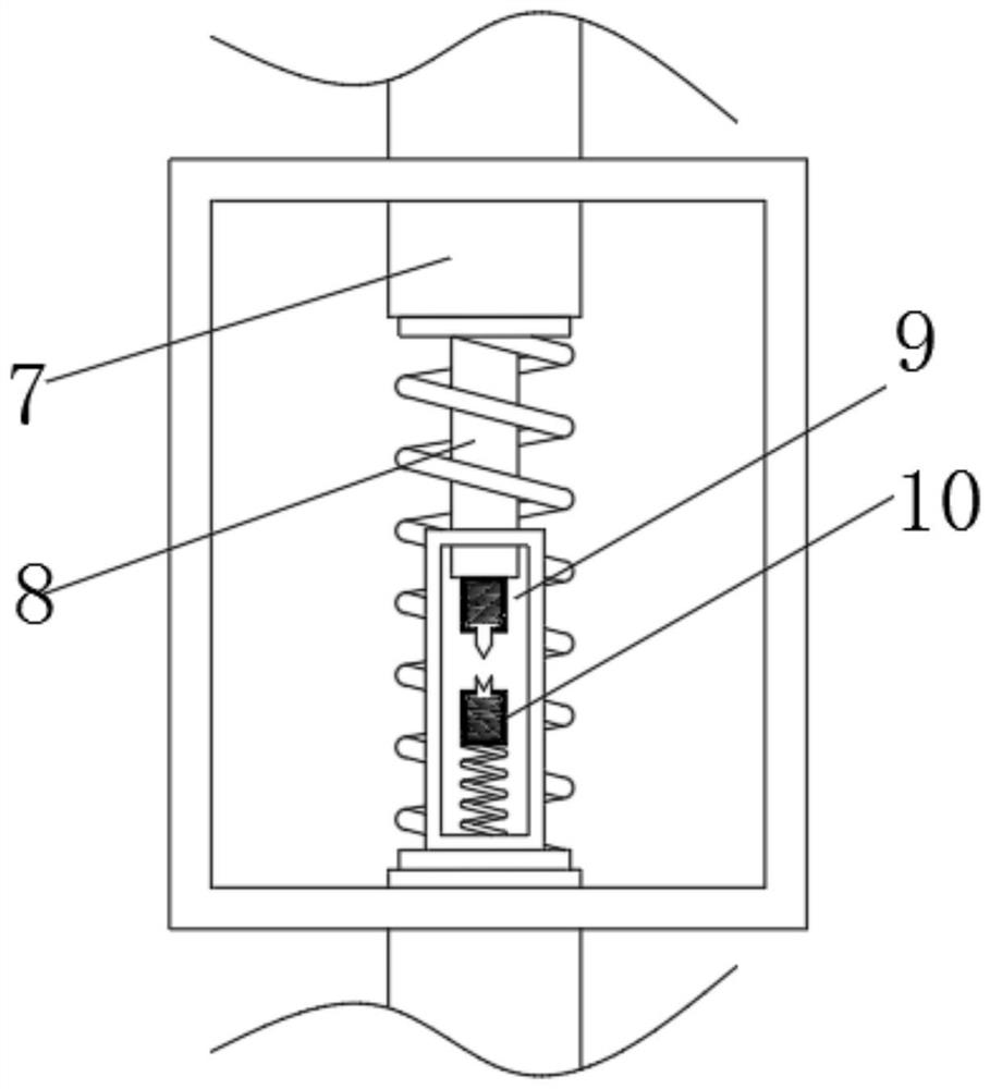
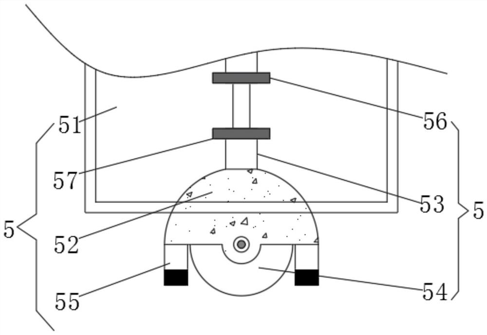
[0028] see figure 1 or image 3 , an electromechanical processing device with automatic clamping and automatic cutting and stopping, comprising a device main body 1, a support plate 2 is fixedly connected to the inside of the device main body 1, a fixing seat 3 is fixedly connected to the upper end of the support plate 2, and the internal movement of the device main body 1 A processing table 4 is connected, and a connecting rod 7 is fixedly connected to the bottom of the processing table 4. The connecting rod 7 is fixedly connected to the first electrode 9 through a T-shaped rod 8. A second electrode 10 is arranged below the first electrode 9. The main body of the device 1 There is a cut-off mechanism 5 connected to the inside of the cut-off mechanism 5. The cut-off mechanism 5 includes a protective shell 51. A wheel shell 52 is slidably connected to the inside of the protective shell 51. The lower end of the wheel shell 52 is fixedly connected to two photoresistors 55, and th...
Embodiment 2
[0030] Please refer to Figure 1-2 or Figure 4-5 , an electromechanical processing device with automatic clamping and automatic cutting and stopping, comprising a device main body 1, a support plate 2 is fixedly connected to the inside of the device main body 1, a fixing seat 3 is fixedly connected to the upper end of the support plate 2, and the internal movement of the device main body 1 A processing table 4 is connected, and a connecting rod 7 is fixedly connected to the bottom of the processing table 4. The connecting rod 7 is fixedly connected to the first electrode 9 through a T-shaped rod 8. A second electrode 10 is arranged below the first electrode 9. The main body of the device 1 There is a cut-off mechanism 5 clamped inside the fixed seat 3, and a clamping mechanism 6 is movably connected to the outside of the fixed seat 3. The clamping mechanism 6 includes a motor 61, and the external rotation of the motor 61 is connected to a screw rod 62, and the external meshin...
Embodiment 3
[0032] Please refer to Figure 1-5 , an electromechanical processing device with automatic clamping and automatic cutting and stopping, comprising a device main body 1, a support plate 2 is fixedly connected to the inside of the device main body 1, a fixing seat 3 is fixedly connected to the upper end of the support plate 2, and a cutting and stopping mechanism 5 includes a protection Shell 51, the inside of the protective shell 51 is slidingly connected with a wheel shell 52, the upper end of the wheel shell 52 is fixedly connected with a telescopic column 53, and the telescopic column 53 is movably connected inside the device main body 1, and the lower end of the wheel shell 52 is fixedly connected with a photoresistor 55 The lower end of the wheel shell 52 is fixedly connected with two photoresistors 55, the inside of the wheel shell 52 is rotatably connected with a cutting wheel 54, and the outside of the telescopic column 53 is fixedly connected with a first magnet 56 and ...
PUM
 Abstract
Description
Claims
Application Information
 - R&D
- Intellectual Property
- Life Sciences
- Materials
- Tech Scout
- Unparalleled Data Quality
- Higher Quality Content
- 60% Fewer Hallucinations
Browse by: Latest US Patents, China's latest patents, Technical Efficacy Thesaurus, Application Domain, Technology Topic, Popular Technical Reports.
© 2025 PatSnap. All rights reserved.Legal|Privacy policy|Modern Slavery Act Transparency Statement|Sitemap|About US| Contact US: help@patsnap.com


