Energy-saving and efficient wind power generation blade unit

A technology of wind power generation blades and units, applied in the field of wind energy, can solve the problems of fan blade running wear and wind power can not be well utilized, and achieve the effect of preventing mechanical wear

Inactive Publication Date: 2022-03-18
象山县船舶舾装件厂
View PDF0 Cites 2 Cited by
  • Summary
  • Abstract
  • Description
  • Claims
  • Application Information

AI Technical Summary

Problems solved by technology

[0005] Aiming at the deficiencies of the prior art, the present invention provides an energy-saving and high-efficiency wind power generation blade unit, which is equipped with the fan blades of the wind power generator to automatically rotate with the wind direction, and at the same time, when the wind force is too strong, the rotating shaft is automatically lubricated, The advantage of preventing mechanical wear solves the problem that the existing wind turbines are generally fixed in a certain direction and only receive force in one direction, which cannot make good use of the wind force in other directions, and at the same time, it is easier for the fan blades to operate in the direction of wind wear-and-tear problems

Method used


Image

  • Energy-saving and efficient wind power generation blade unit
  • Energy-saving and efficient wind power generation blade unit
  • Energy-saving and efficient wind power generation blade unit

Examples


Embodiment 1

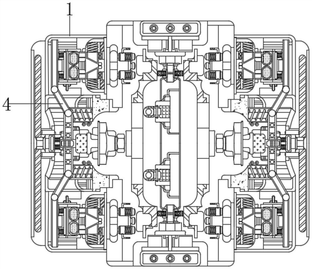
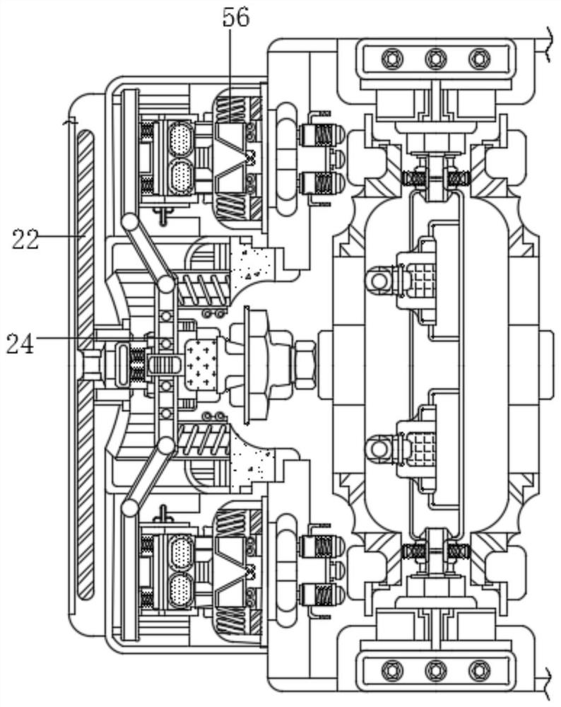
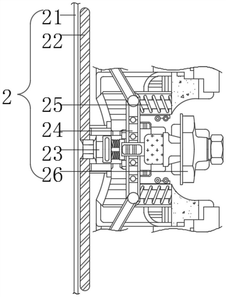
[0025] see figure 1 , figure 2 , image 3 ,and Figure 4 , an energy-saving and high-efficiency wind power generation blade unit, comprising a casing 1, a push mechanism 2 is movably connected to the left end of the casing 1, and the inside of the push mechanism 2 includes an air gathering port 21, and a force plate 22 is movably connected to the right end of the wind gathering port 21, and the force receiving The right end of plate 22 is fixedly connected with connection block 23, and the right end of connection block 23 is fixedly connected with guide rod 24, and the right end of guide rod 24 is movably connected with compression spring 25, and the right end of guide rod 24 is fixedly connected with top block 26, and there are two top blocks 26, And with respect to the inner center line of the housing 1, the left and right are symmetrical, the top block 26 is located at the left end of the trigger ring 31, the force plate 22 is located at the left end of the inner wall of...

Embodiment 2

[0028] see figure 1 , figure 2 , image 3 ,and Figure 5 , an energy-saving and high-efficiency wind power generation blade unit, comprising a casing 1, a push mechanism 2 is movably connected to the left end of the casing 1, a steering mechanism 3 is movably connected to the right end of the push mechanism 2, and a tension rod 4 is movably connected to the upper end of the push mechanism 2, and the pulling force The upper end of the rod 4 is movably connected with a lubricating mechanism 5. The inside of the lubricating mechanism 5 includes a moving rod 51. The right end of the moving rod 51 is fixedly connected with a buffer spring 52. The right end of the buffer spring 52 is fixedly connected with a pressure rod 53. The right end of the pressure rod 53 is movably connected with a lubricating oil tank. 54. The right end of the lubricating oil tank 54 is fixedly connected with a conduit 55, and the right end of the conduit 55 is movably connected with a blocking mechanism ...

Embodiment 3

[0031] see Figure 1-5, an energy-saving and high-efficiency wind turbine blade unit, comprising a casing 1, a pushing mechanism 2 is movably connected to the left end of the casing 1, and the pushing mechanism 2 includes an air collecting port 21, and the right end of the air collecting port 21 is movably connected with a force-bearing plate 22, which receives the force A connecting block 23 is fixedly connected to the right end of the plate 22, a guide rod 24 is fixedly connected to the right end of the connecting block 23, a compression spring 25 is movably connected to the right end of the guide rod 24, and a top block 26 is fixedly connected to the right end of the guide rod 24. There are two top blocks 26. , and is symmetrical about the inner center line of the shell 1, the top block 26 is located at the left end of the trigger ring 31, the force plate 22 is located at the left end of the inner wall of the shell 1, the left end of the shell 1 is provided with a force plat...


PUM


Abstract

The invention relates to the technical field of wind energy, and discloses an energy-saving and efficient wind power generation blade unit which comprises a shell, a pushing mechanism is movably connected to the left end of the shell, a steering mechanism is movably connected to the right end of the pushing mechanism, a tension bar is movably connected to the upper end of the pushing mechanism, and a lubricating mechanism is movably connected to the upper end of the tension bar. Through triggering of an internal contact of the triggering mechanism, an external driving source enables a steering shaft to rotate, then a positioning block is driven to rotate together, when the positioning block rotates to the right end, the positioning block exerts thrust on the inner wall of a triggering ring at the moment, the triggering ring moves rightwards, and then the pressing force of the triggering ring on the triggering mechanism disappears; therefore, the external driving source stops moving, the steering shaft rotates to a proper angle, the fan blades of the wind driven generator rotate to the windward direction, and the effect that the fan blades of the wind driven generator automatically rotate along with the wind direction is achieved.

Description

technical field [0001] The invention relates to the technical field of wind energy, in particular to an energy-saving and high-efficiency wind power generation blade unit. Background technique [0002] With the gradual development of society, people's living standards have been significantly improved, and the consumption of energy is also increasing. With the decreasing of non-renewable energy, people are gradually using renewable energy such as wind energy and geothermal energy. Among them, the utilization of wind energy has gradually tended to be universal. [0003] However, at present, there are still defects that need to be overcome in the operation of wind power generation. Wind power generation uses wind energy to blow the fan blades, thereby generating electricity through magnetism, but the existing wind power generators are generally fixed in a certain direction. , only one-way force, can not make good use of the wind in other directions, and at the same time, the b...

Claims


Application Information

Patent Timeline
Patent Type & Authority Applications(China)
IPC IPC(8): F03D1/06F03D7/02F03D7/04F03D80/00
CPCF03D1/0675F03D1/0633F03D7/0204F03D7/04F03D80/00Y02E10/72
Inventor 郑志节
Owner 象山县船舶舾装件厂
Why Eureka
Try Eureka