
Eccentric adjusting device

A technology of eccentricity adjustment and centerline, which is applied in installation, instrumentation, optics, etc., and can solve the problems of poor follow-up performance of aspheric lenses, relatively high requirements for ferrule processing, and long adjustment time, etc.

Active Publication Date: 2022-03-18
ZHUHAI AUTO VISION TECH CO LTD
View PDF4 Cites 0 Cited by
  • Summary
  • Abstract
  • Description
  • Claims
  • Application Information

AI Technical Summary

Problems solved by technology

[0003] The existing eccentricity adjustment usually uses a ferrule matching the shape of the lens to clamp the aspheric lens, and then uses the XY axis sliding platform to adjust the position of the aspheric lens in the lens module, that is, to adjust the position of the lens to be adjusted. position, other lens positions do not need to be adjusted, this method has relatively high processing requirements for the ferrule, and the adjusted aspheric lens has poor follow-up performance, resulting in a relatively long adjustment time

Method used


Image

  • Eccentric adjusting device

Examples


Embodiment Construction

[0021] Embodiments of the present invention are described in detail below, and examples of the embodiments are shown in the drawings, wherein the same or similar reference numerals denote the same or similar elements or elements having the same or similar functions throughout. The embodiments described below by referring to the figures are exemplary only for explaining the present invention and should not be construed as limiting the present invention.

[0022] In the description of the present invention, it should be understood that the orientation descriptions, such as up, down, front, back, left, right, etc. indicated orientation or positional relationship may be based on the orientation or positional relationship shown in the accompanying drawings, only It is for the convenience of describing the present invention and simplifying the description, but does not indicate or imply that the referred device or element must have a specific orientation, be constructed and operated ...


PUM


Abstract

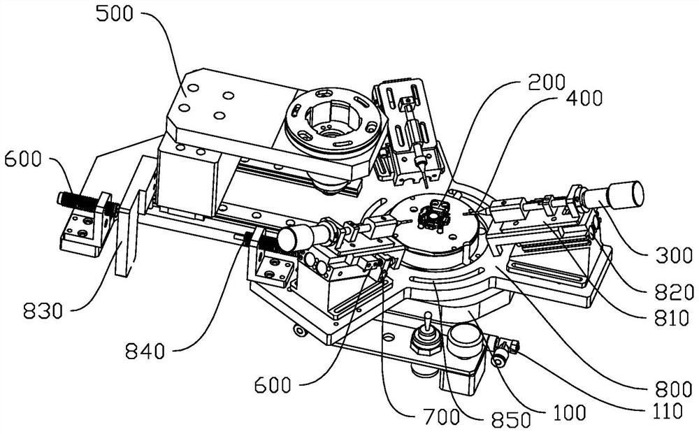
The invention discloses an eccentric adjusting device which comprises a base, a metal group and three ejector pins, a lens positioning seat is arranged on the base, a light-transmitting area transmitting light in the vertical direction is arranged at the center line of the lens positioning seat, the light-transmitting area can directly face a lens to be adjusted, and three linear fine adjusting mechanisms are arranged in the area, around the center line, of the base; the three ejector pins are arranged on the base and distributed around the center line, the tip ends of the three ejector pins face downwards and point to the center line, the output ends of the three linear fine adjustment mechanisms are connected with the connecting ends of the three ejector pins respectively to drive the ejector pins to slide in the length direction of the ejector pins, and the tip ends of the ejector pins can abut against the peripheral side of a to-be-adjusted lens; the upper end of the metal group is provided with a limiting through hole used for limiting other lenses, and the metal group is arranged on the base in a sliding mode so that the limiting through hole can be located above the light-transmitting area and the ejector pin. The position, the height position, the inclination direction and the inclination angle of the to-be-adjusted lens on the horizontal plane can be adjusted through the three ejector pins, convenience and rapidness are achieved, and the adjusting precision is high.

Description

technical field [0001] The invention relates to the technical field of optical devices, in particular to an eccentricity adjustment device. Background technique [0002] In the optical industry, lenses are an indispensable part. Lenses have superior optical properties and mechanical and chemical properties, have a constant refractive index, and have stable physical and chemical properties. A lens module generally includes multiple lenses, and each lens will inevitably have an optical axis shift. The eccentricity of the aspheric lens in the optical system has the greatest impact on the imaging quality, which reduces the contrast of the entire optical system and the resolution. Poor and low definition, and even cause the lens module to fail. In order to improve the imaging quality of the optical system, optical decentering detection and adjustment are usually performed on the sensitive aspheric lens. [0003] The existing eccentricity adjustment usually uses a ferrule matchi...

Claims


Application Information

Patent Timeline
Patent Type & Authority Applications(China)
IPC IPC(8): G02B7/02
CPCG02B7/023
Inventor 朱礼平龚博喻超凡曾胜
Owner ZHUHAI AUTO VISION TECH CO LTD
Learn More