Automatic heat dissipation and cooling mechanism for new energy automobile generator

A technology for new energy vehicles and generators, applied in electric components, electrical components, electromechanical devices, etc., can solve the problems of low reliability, low operating frequency of generators, and inability to effectively dissipate heat, so as to improve reliability, The effect of improving the heat dissipation effect

Active Publication Date: 2022-03-18
TIANCHANG TIANFENG MECHANICAL & ELECTRICAL TECH CO LTD
View PDF9 Cites 0 Cited by
  • Summary
  • Abstract
  • Description
  • Claims
  • Application Information

AI Technical Summary

Problems solved by technology

Only when the car brakes by itself will it drive the generator to generate electricity. In some congested roads, the car needs to brake frequently. The working frequency of the new energy vehicle generator is very low, so it will not generate much heat, and there is no need for heat dissipation. Therefore, there is a large span in the heat generation of the new energy vehicle generator, and the current heat dissipation mechanism of the new energy vehicle generator cannot effectively cope with this large span. In the case of heat generation, either the heat dissipation consumes a large amount of power, or cannot effectively dissipate heat, which affects the service life of the generator and leads to low reliability

Method used


Image

  • Automatic heat dissipation and cooling mechanism for new energy automobile generator
  • Automatic heat dissipation and cooling mechanism for new energy automobile generator
  • Automatic heat dissipation and cooling mechanism for new energy automobile generator

Examples


Embodiment Construction

[0032] The following will clearly and completely describe the technical solutions in the embodiments of the present invention with reference to the accompanying drawings in the embodiments of the present invention. Obviously, the described embodiments are only some, not all, embodiments of the present invention. Based on the embodiments of the present invention, all other embodiments obtained by persons of ordinary skill in the art without making creative efforts belong to the protection scope of the present invention.

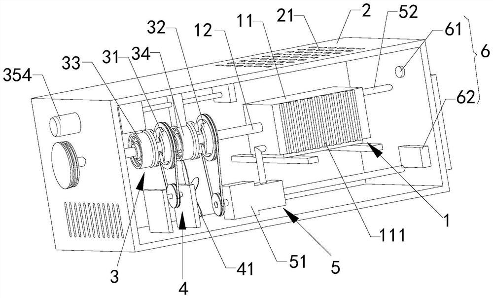
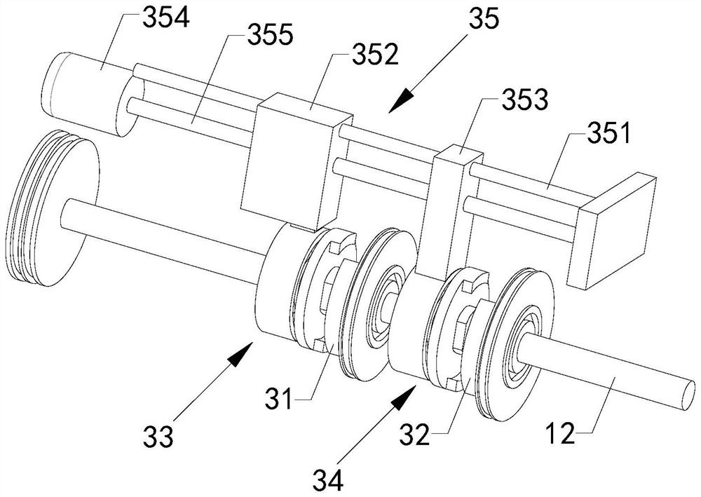
[0033] see Figure 1-5 , the embodiment of the present application provides a new energy vehicle generator 11 automatic heat dissipation and cooling mechanism, which is arranged on the generator mechanism 1. The generator mechanism 1 includes a generator 11 and a rotating shaft 12 arranged at the power input end of the generator 11 to automatically dissipate heat Cooling agencies include:

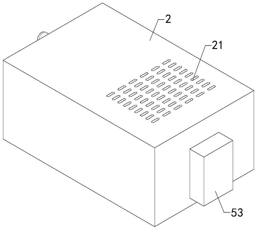
[0034] The box body 2 has a cavity and an air outlet 21 and an air in...


PUM


Abstract

The invention relates to a new energy automobile generator automatic heat dissipation and cooling mechanism which is arranged on a generator mechanism, the generator mechanism comprises a generator and a rotating shaft arranged at the power input end of the generator, and the automatic heat dissipation and cooling mechanism comprises a box body, a transmission mechanism, an air cooling mechanism and a liquid cooling mechanism. The box body is provided with a cavity, an air outlet and an air inlet, the air outlet and the air inlet are communicated with the cavity, and the transmission mechanism comprises a first fixed meshing sleeve, a second fixed meshing sleeve, a first clutch assembly, a second clutch assembly and a driving assembly. The driving assembly is used for driving the first clutch assembly to be meshed with or separated from the first fixed meshing sleeve and driving the second clutch assembly to be meshed with or separated from the second fixed meshing sleeve; the air cooling mechanism comprises a heat dissipation fan arranged at the air inlet, the liquid cooling mechanism comprises a circulating pump, a cooling coil and a cooling water tank, the situation that the span of the heating range of the generator is large can be effectively handled, effective heat dissipation can be carried out, the power consumed by heat dissipation can be effectively controlled, and the use reliability is improved.

Description

technical field [0001] The invention relates to the technical field of generator heat dissipation, in particular to an automatic heat dissipation and cooling mechanism for a generator of a new energy vehicle. Background technique [0002] In recent years, the proportion of new energy vehicles has become higher and higher. Currently, new energy vehicles are generally equipped with energy recovery systems, that is, a part of energy is recovered through self-braking, and the energy is converted into electrical energy through a generator and stored in a power battery. Only when the car brakes by itself will it drive the generator to generate electricity. In some crowded roads, the car needs to brake frequently, and the working frequency of the generator is high, so the self-heating is serious. The working frequency of the generator is very low, so it will not generate much heat, and there is no need to dissipate heat. Therefore, there is a large span in the heat generation of th...

Claims


Application Information

Patent Timeline
IPC IPC(8): H02K9/19H02K9/06H02K7/10H02K5/04H02K5/20
CPCH02K9/06H02K9/19H02K7/10H02K5/04H02K5/207
Inventor 徐乐高黄大军张厚明
Owner TIANCHANG TIANFENG MECHANICAL & ELECTRICAL TECH CO LTD
Why Eureka
Try Eureka