Clamp and method for fastening a clamp

A technology of clamps and clamping bands, applied in the direction of flange connection, through components, couplings, etc., can solve problems such as damage to functions

Pending Publication Date: 2022-03-18
NORMA GERMANY GMBH
View PDF7 Cites 0 Cited by
  • Summary
  • Abstract
  • Description
  • Claims
  • Application Information

AI Technical Summary

Problems solved by technology

In this case, it is important that the tensioning element is tensioned in a prescribed manner, since both overtensioning and undertensioning can seriously impair the function

Method used


Image

  • Clamp and method for fastening a clamp
  • Clamp and method for fastening a clamp

Examples


Embodiment Construction

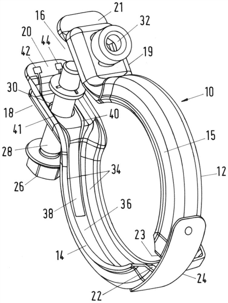
[0049] figure 1 A perspective view of a clamp 10 is shown in an open state prior to installation. The clamp 10 has a clamping strip 12 divided into two half clamps 14, 15, wherein at an opening 16 of the clamp 10, ends 18, 19 is bent to form a plurality of tensioning heads 20, 21 (which may also be designated as split flanges) so that the ends 18, 19 abut each other when the clamp 10 is closed.

[0050] At their ends 22 opposite the tensioning heads, the two clamp halves 14, 15 are connected to each other in an articulated manner by means of a connecting piece 24, so that the clamp 10 The opening 16 can be widened by pivoting the clamp halves 14, 15 in opposite directions in order to place the clamp 10 on a plurality of pipe elements (not shown).

[0051] The two tensioning heads 20, 21 can be clamped to each other by means of a tensioning screw 28, here serving as a tensioning element 26, wherein on the tensioning head 20 all parts of said tensioning screw 28 are provided. ...


PUM


Abstract

The invention relates to a clamp for fixing a hose or pipe element, comprising an endless clamping band (12) having at least one opening (16). The clamp (10) has a closed state and an open state, and the clamp is firmly clamped in an installation position. The clamp (10) has a radio frequency identification chip (38) connected to a switching circuit, wherein the switching state of the switching circuit is related to the closed state and the open state of the clamp (10). In at least one on-off state, a data set can be read from the radio frequency identification chip, and / or the plurality of readable data sets of the radio frequency identification chip are different according to the on-off state.

Description

technical field [0001] According to the preamble of claim 1, the invention relates to a clamp for fixing hose or pipe elements, comprising an annular clamping band with at least one opening, wherein the clamp has a closed state and an open state, and are securely clamped in an installed position. The subject of the invention is also a method of mounting a clamp of this type. Background technique [0002] This type of clamp is common in various embodiments. They are used, inter alia, in automobile construction to hold pipes and hoses in specific positions, even under load, and to connect pipe elements to each other in a fluid-tight manner at joints . In this case, it is important that the tensioning element is tensioned in a defined manner, since both overtensioning and undertensioning can seriously impair the function. [0003] In the prior art it is known to program the installation robot such that the tensioning element, usually a tensioning screw, is set to the correc...

Claims


Application Information

Patent Timeline
Patent Type & Authority Applications(China)
IPC IPC(8): F16L23/08
CPCF16L23/08F16L2201/10
Inventor 马特乌斯·雅罗斯
Owner NORMA GERMANY GMBH
Why Eureka
Try Eureka