Displacement workbench

A workbench and displacement technology, which is applied in the field of welding processing, can solve the problems of increased shaft transmission torque load of the overturn drive motor, affecting the service life of the overturn drive motor, and affecting the welding effect of the workpiece, so as to reduce the shaft transmission torque and the working position. The effect of stability and low manufacturing cost

Pending Publication Date: 2022-03-22
FOSHAN HUIBAISHENG LASER TECH CO LTD
View PDF6 Cites 2 Cited by
  • Summary
  • Abstract
  • Description
  • Claims
  • Application Information

AI Technical Summary

Problems solved by technology

Similarly, after the workbench is turned over for welding, the workbench is not turned over and locked. On the one hand, the shaft transmission torque load of the turning drive motor will increase, which will affect the service life of the turning drive motor. On the other hand, during the processing, The contact between the workpiece and the welding head will exert an external force on the worktable, which will easily cause the rotation of the turning axis, thereby changing the turning angle and affecting the welding effect of the workpiece

Method used


Image

  • Displacement workbench
  • Displacement workbench
  • Displacement workbench

Examples


Embodiment Construction

[0033] The present invention provides a displacement workbench. In order to make the purpose, technical solution and effect of the present invention clearer and clearer, the present invention will be further described in detail below with reference to the accompanying drawings and examples. It should be understood that the specific embodiments described here are only used to explain the present invention, and are not intended to limit the protection scope of the present invention.

[0034] In this paper, the direction of the loading and unloading area towards the welding area is "front", and "front" and "rear" are opposite.

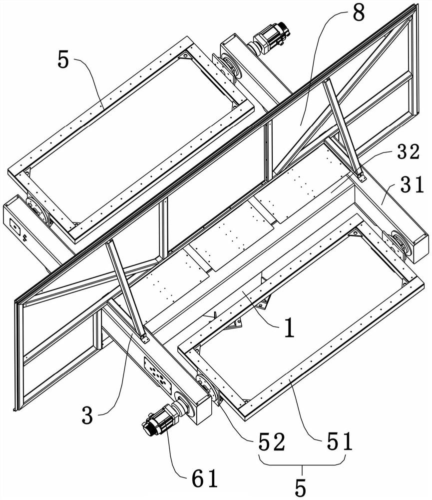
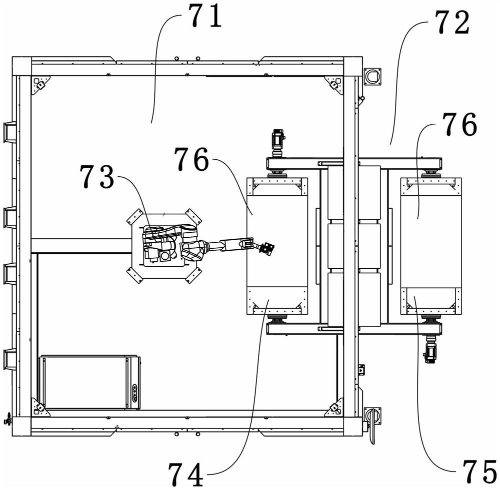
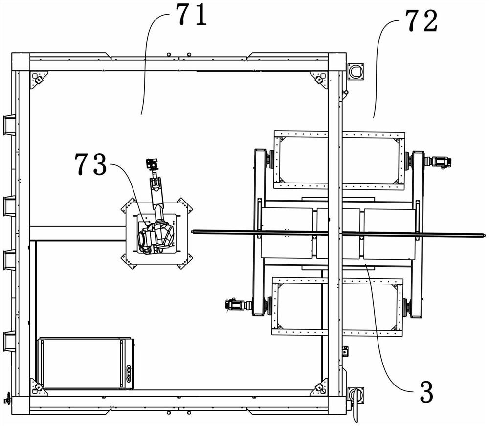
[0035] see Figure 1-Figure 4 , the present invention provides a displacement workbench comprising a platform 3 with double stations, a driving base 1 arranged at the bottom of the platform 3 and used to drive the rotation of the platform 3, and two symmetrically arranged on the driving base 1 The station positioning module 2; each station of the platfor...


PUM


Abstract

The invention relates to the technical field of welding machining, and particularly discloses a displacement workbench which comprises a rack with double stations, a driving base table used for driving the rack to rotate and two station positioning modules symmetrically arranged on the driving base table. A turnover swing frame, a swing frame driving mechanism for driving the swing frame to turn over and a disc brake structure for braking the swing frame are arranged at each station of the rack; the station positioning module comprises a positioning block, a positioning support, a limiting piece arranged on the positioning support and a displacement sensor arranged beside the limiting piece, the positioning block is installed at the bottom of the rack, and a displacement sensing piece is arranged on the positioning block; and a locking mechanism and a buffer structure are arranged on the positioning support. According to the displacement workbench, rotation locking and overturning locking are conducted on the rack through the disc brake structure and the locking mechanism, the stability of the rack is improved, and the welding effect is ensured.

Description

[0001] This application is a divisional application of the patent application with the patent application number "202111036231.4", the application date is "September 6, 2021", and the title is "a kind of displacement workbench". technical field [0002] The invention relates to the technical field of welding processing, in particular to a displacement workbench. Background technique [0003] The shifting table is a kind of equipment that cooperates with the welding manipulator to realize automatic laser welding. The shifting table will make the workpieces to be processed enter the welding area through a predetermined rotation to realize welding processing, and the processed workpieces will be rotated synchronously to the loading and unloading area. Then the station performs loading and unloading operations. After the existing shifting workbench is rotated into place, the workbench is generally not rotated and locked. During the workpiece processing or loading and unloading pr...

Claims


Application Information

Patent Timeline
Patent Type & Authority Applications(China)
IPC IPC(8): B23K26/70B23K26/21
CPCB23K26/21B23K26/702
Inventor 梁建冬练振达廖谷祥左建林黄海涛李宏鑫刘锦均黄思薪杨红杰严君仪罗勇杰杨广潮苏伟瞬林哲肖冲王红胜吴昌坚
Owner FOSHAN HUIBAISHENG LASER TECH CO LTD
Why Eureka
Try Eureka