Workbench positioning module

A positioning module and worktable technology, applied in the direction of precision positioning equipment, manufacturing tools, large fixed members, etc., can solve the problems of changing the processing position of the workpiece, affecting the processing accuracy, poor applicability, etc., to reduce positioning errors, low production costs, The effect of low manufacturing cost

Pending Publication Date: 2021-12-10
佛山汇百盛激光科技有限公司
View PDF0 Cites 1 Cited by
  • Summary
  • Abstract
  • Description
  • Claims
  • Application Information

AI Technical Summary

Problems solved by technology

For example, in the rotary double-station conversion, the driving device of the worktable is actually a cam indexer, and the worktable is installed horizontally on the main shaft of the cam indexer. conversion, but the cam indexer on the market has a small load capacity and cannot be used with a heavy-duty workbench, and the transmission structure of the cam indexer is complex and the purchase cost is high
In addition, since the cam indexer can only rotate at a specific angle, the position of the workbench cannot be fine-tuned, and only the position of the processing equipment can be adjusted to match it, which has poor applicability
[0003] Secondly, since there is no locking structure to lock and restrict the workbench after the work station is in place, the workbench may vibrate or shift under the transmission of external processing loads during processing, thus changing the position of the work station , which in turn changes the machining position of the workpiece and affects the machining accuracy

Method used


Image

  • Workbench positioning module
  • Workbench positioning module
  • Workbench positioning module

Examples


Embodiment Construction

[0024] The present invention provides a workbench positioning module. In order to make the purpose, technical solution and effect of the present invention more clear and definite, the present invention will be further described in detail below with reference to the accompanying drawings and examples. It should be understood that the specific embodiments described here are only used to explain the present invention, and are not intended to limit the protection scope of the present invention.

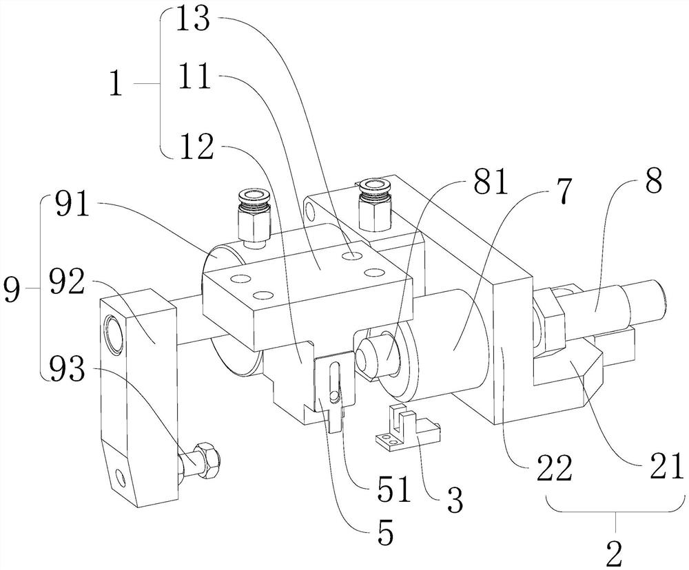
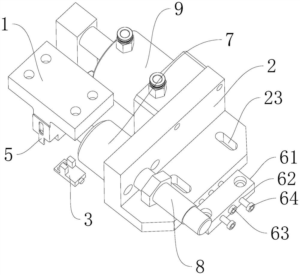
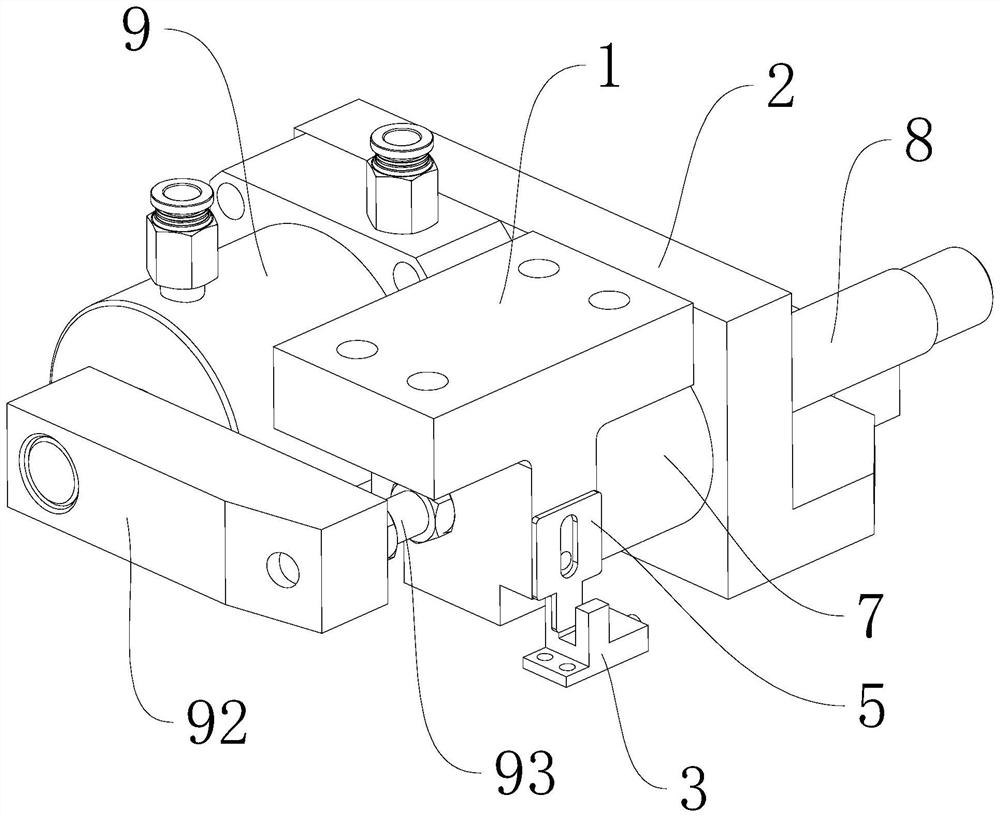
[0025] see Figure 1-Figure 3 , the present invention provides a workbench positioning module, including a positioning block 1, a positioning support 2, a limiting member 7 arranged on the positioning support 2, and a sensor 3 arranged on the side of the limiting member. The positioning block 1 is installed On the workbench 4, the positioning block 1 is provided with a trigger assembly, and the trigger assembly is used to trigger the sensor 3; Locking mechanism; the positioning support 2...


PUM


Abstract

The invention discloses a workbench positioning module. The workbench positioning module comprises a positioning block, a positioning support, a limiting piece arranged on the positioning support and a sensor arranged on one side of the limiting piece, and a triggering assembly for triggering the sensor is arranged on the positioning block; a locking mechanism for pressing the positioning block on the limiting piece is arranged on the positioning support; and the positioning support is provided with a buffer structure used for reducing the speed of the positioning block. According to a workbench, the positioning block is additionally arranged on the workbench, the triggering assembly on the positioning block triggers the sensor to send out a braking signal, response is sensitive, a specific controller is not needed, the manufacturing cost is low, then the positioning block is buffered through the buffering structure and then matched with the limiting piece for positioning, and then the positioning block is locked through the locking mechanism; on the one hand, the limiting piece is attached to the positioning block, positioning is accurately completed, and positioning errors are greatly reduced; and on the other hand, the position of the positioning block is locked, and it is guaranteed that the workbench cannot move automatically in the machining process.

Description

technical field [0001] The invention relates to the technical field of workbench control, in particular to a workbench positioning module. Background technique [0002] In order to improve processing efficiency, multi-stations will be set up on the workbench according to actual needs, and the stations loaded with workpieces will be driven to the processing area by the drive device of the workbench, and then the processing equipment will process the workpieces. For example, in the rotary double-station conversion, the driving device of the worktable is actually a cam indexer, and the worktable is installed horizontally on the main shaft of the cam indexer. However, the load capacity of cam indexers on the market is too small to be used with heavy-duty workbenches, and the transmission structure of cam indexers is complicated and the purchase cost is high. In addition, since the cam indexer can only rotate at a specific angle, the position of the workbench cannot be fine-tune...

Claims


Application Information

Patent Timeline
Patent Type & Authority Applications(China)
IPC IPC(8): B23Q1/26B23Q1/00B23Q16/00
CPCB23Q1/26B23Q1/0018B23Q16/00
Inventor 梁建冬练振达廖谷祥左建林黄海涛李宏鑫刘锦均黄思薪杨红杰严君仪罗勇杰杨广潮苏伟瞬林哲肖冲王红胜吴昌坚
Owner 佛山汇百盛激光科技有限公司
Why Eureka
Try Eureka