Design method of composite transformer water cooling tool

A composite transformer and design method technology, applied in workpiece clamping devices, manufacturing tools, etc., can solve the problems of reduced overall performance of tooling, low rigidity of tooling body, reduced machining accuracy, etc., so as to reduce machining costs and material costs. , the effect of reducing the use of materials

Pending Publication Date: 2022-03-22
BAODING TIANWEI BAOBIAN ELECTRICAL
View PDF0 Cites 0 Cited by
  • Summary
  • Abstract
  • Description
  • Claims
  • Application Information

AI Technical Summary

Problems solved by technology

[0004] In order to make up for the deficiencies of the existing technology, the existing tooling is relatively large in size and the rigidity of the tooling body is relatively low. During machining, the lower rigidity of the tooling body affects the machining accuracy and reduces the machining accuracy. To solve the problem of lower overall performance of the tooling, the present invention proposes a design method for the water-cooled tooling of the composite transformer

Method used


Image

  • Design method of composite transformer water cooling tool
  • Design method of composite transformer water cooling tool
  • Design method of composite transformer water cooling tool

Examples


Embodiment 1

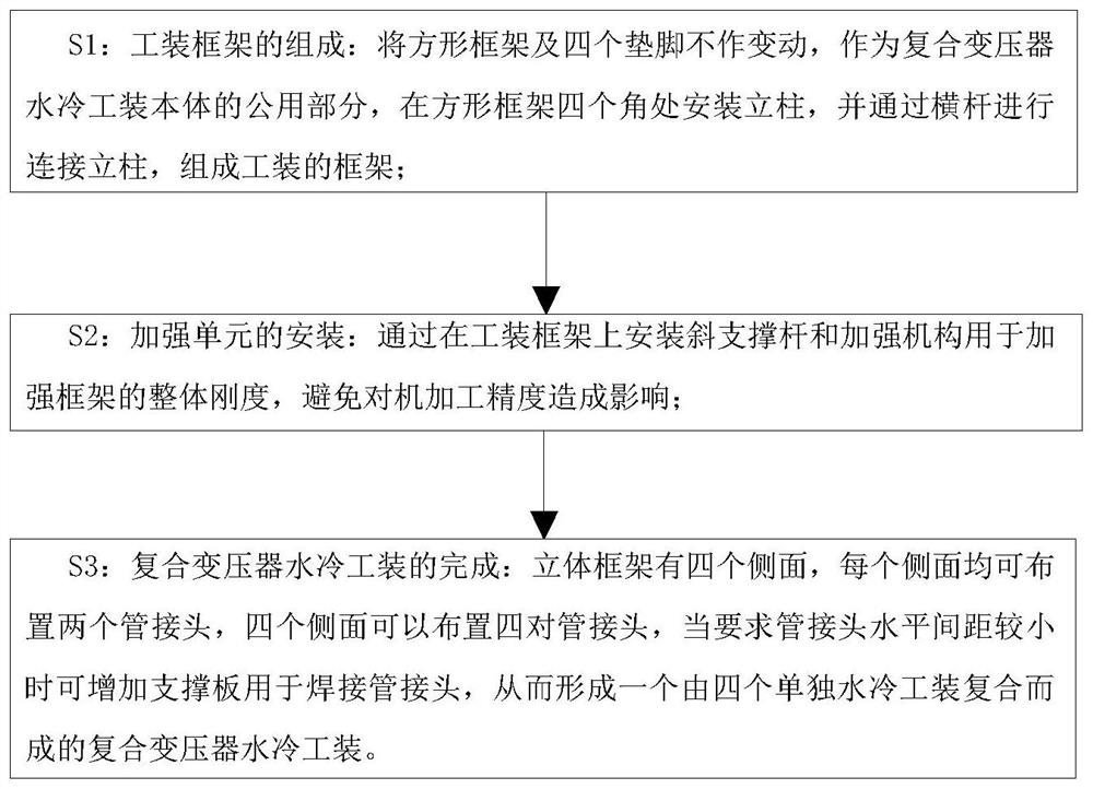
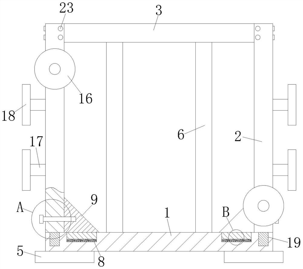
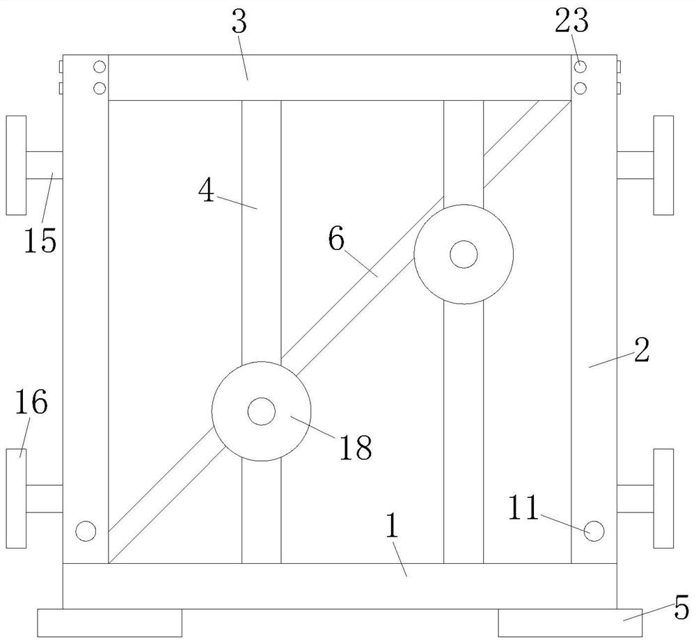
[0033] see Figure 1-7 As shown, a design method of composite transformer water-cooled tooling, the design method includes the following steps:

[0034] S1: The composition of the tooling frame: the square frame and four feet are not changed, and as the common part of the composite transformer water-cooled tooling body, columns are installed at the four corners of the square frame, and the columns are connected by cross bars to form the frame of the tooling;

[0035] S2: Installation of strengthening unit: Installing inclined support rods and strengthening mechanisms on the tooling frame is used to strengthen the overall rigidity of the frame to avoid affecting the machining accuracy;

[0036] S3: Completion of the composite transformer water-cooling tooling: the three-dimensional frame has four sides, and two pipe joints can be arranged on each side, and four pairs of pipe joints can be arranged on the four sides. When the horizontal distance between the pipe joints is requir...

Embodiment 2

[0047] see Figure 8 As shown in Comparative Example 1, as another embodiment of the present invention, an anti-skid pad 25 is fixedly attached to the bottom of the feet 5; the anti-skid pad 25 is made of rubber; 25 Increase the frictional force between the pad foot 5 and the contact part of the placement plane, so that the overall placement of the frock is more stable and not easy to slip.

[0048] Working principle: insert the second threaded rod 20 into the third threaded hole 19, through the cooperation between the second threaded rod 20 and the third threaded hole 19, the column 2 is fixedly installed on the top of the square frame 1, the installation method is simple and convenient, convenient Disassemble, so that the columns 2 are located at the four corners of the square frame 1, and then insert the end of the cross bar 3 into the placement groove 21, so that the threaded through hole 22 is aligned with the fourth threaded hole 24, and turn the third threaded rod 23 ,...


PUM


Abstract

The invention belongs to the technical field of power transformer oil tank machining, and particularly relates to a design method of a composite transformer water-cooling tool, which comprises the following steps: S1, forming a tool frame: keeping a square frame and four foot pads unchanged, mounting stand columns at four corners of the square frame, and connecting the stand columns through cross rods, forming a frame of the tool; s2, installation of reinforcing units, wherein inclined supporting rods and reinforcing mechanisms are installed on the tool frame to reinforce the overall rigidity of the frame; s3, the composite transformer water cooling tool is completed, specifically, the three-dimensional frame is provided with four side faces, four pairs of pipe joints can be arranged on the four side faces, and therefore the composite transformer water cooling tool formed by compositing four independent water cooling tools is formed; the inclined supporting rods and the reinforcing mechanisms are arranged to reinforce the three-dimensional frame, and the situation that the machining precision is affected due to the fact that the overall rigidity of a tool is low during machining is avoided.

Description

technical field [0001] The invention relates to the technical field of power transformer oil tank processing, in particular to a design method of a composite transformer water-cooling tooling. Background technique [0002] In the process of making transformer oil tanks, it is often necessary to make water cooler tooling to simulate a real water cooler to facilitate the preparation of joint pipes. The water cooling tooling is assembled from two pipe joints and the tool body. The flange connection surfaces of the two pipe joints are located in the same plane and are perpendicular to the bottom surface of the feet. Both the bottom surface of the feet and the flange connection surfaces of the two pipe joints need to be machined. [0003] In the current existing technology, due to the large size of the existing tooling, the rigidity of the tooling body is relatively low. During machining, the lower rigidity of the tooling body affects the machining accuracy, reduces the machining...

Claims


Application Information

Patent Timeline
Patent Type & Authority Applications(China)
IPC IPC(8): B25B11/00
CPCB25B11/00
Inventor 张胜利秦建伟曹伟龙孙明明谭明志陈胜云王仕宁康抗崔梦浩
Owner BAODING TIANWEI BAOBIAN ELECTRICAL
Why Eureka
Try Eureka