Total detection machine for gear shifting shaft

A technology of shifting shaft and cover, applied in the testing of mechanical parts, the testing of machine/structural parts, and by detecting the appearance of fluid at the leak point, etc., can solve the problems of inconvenient detection, high cost and low detection efficiency, etc.

Pending Publication Date: 2022-03-22
武汉泛洲精冲有限公司
View PDF0 Cites 1 Cited by
  • Summary
  • Abstract
  • Description
  • Claims
  • Application Information

AI Technical Summary

Problems solved by technology

At present, the shift shaft needs to be tested during the machining process, but the current detection equipment usually adopts manual detection method, the detection efficiency is low, and only one index of the shift shaft can be detected, which is inconvenient and costly. high

Method used


Image

  • Total detection machine for gear shifting shaft
  • Total detection machine for gear shifting shaft
  • Total detection machine for gear shifting shaft

Examples


Embodiment 1

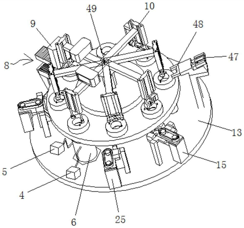
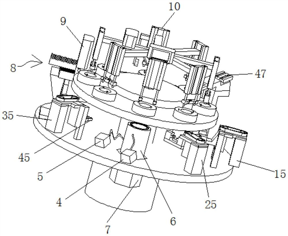
[0041] like Figure 1 to Figure 11As shown, the present embodiment provides a gearshift shaft general inspection machine, including a disk 1, a detection device 1, a detection device 3 and a positioning device. A plurality of detection holes are used to place the shift shaft 3 and penetrate up and down; the positioning device is fixedly erected above the disc 1, and is used to locate the shift shaft 3 at the multiple detection holes; the detection device 1 and the detection device 3 are arranged along the circle The circumferential interval of the disc 1 is installed under the disc 1, the detection device 1 is used to detect whether the shift shaft 3 at the corresponding detection hole is in the neutral position, and the detection device 3 is used to detect the shift shaft 3 at the corresponding detection hole The amount of shifting force when rotating.

[0042] During detection, at first, manually place a plurality of shift shafts 3 to be detected in a plurality of detection...

Embodiment 2

[0051] On the basis of Embodiment 1, this embodiment also includes a detection device five, which is fixedly installed under the disc 1, and is used to detect the airtightness of the shift cover 3-1 on the shift shaft 3 at the corresponding detection hole. The detection device 1, the detection device 3 and the detection device 5 are sequentially distributed along the circumferential direction of the disc 1 at intervals. During detection, the corresponding motor drives the disc 1 to rotate so that the corresponding detection hole rotates to the top of the detection device five, and then the detection device five detects the air tightness of the shift cover 3-1 on the shift shaft 3, which is convenient for detection.

Embodiment 3

[0053] On the basis of Embodiment 2, in this embodiment, the detection device five includes an air tightness detector 4, an air compressor 5, a sealing cylinder 6 and an air tightness detection cylinder 7, and the sealing cylinder 6 is vertically installed on the bottom of the disk 1. Below, it can move up and down, and its upper end is open. The air compressor 5 is fixedly installed on the sealing cylinder 6. It communicates with the inside of the sealing cylinder 6 through a hose, and an air valve is fixedly installed on the pipeline, and the air tightness detection cylinder 7. The air tightness detector 4, the air compressor 5 and the air valve are respectively connected to the controller through lines; the air tightness detection cylinder 7 is fixedly installed on the workbench 13 corresponding to the position below the sealing cylinder 6, and its telescopic end is along the sealing cylinder. 6, and is fixedly connected with the lower end of the sealing cylinder 6, which ca...


PUM


Abstract

The invention relates to a gear-shifting shaft general detection machine, which comprises a disc, a detection device I, a detection device III and a positioning device, and is characterized in that the disc is horizontally and rotatably arranged, and a plurality of detection holes which are used for placing gear-shifting shafts and are through up and down are uniformly formed in the edge of the disc along the circumferential direction at intervals; the positioning device is fixedly erected above the disc and used for positioning the gear shifting shafts at the multiple detection holes. The first detection device and the third detection device are installed below the disc in the circumferential direction of the disc at intervals, the first detection device is used for detecting whether the gear shifting shaft at the corresponding detection hole is located at the neutral gear or not, and the third detection device is used for detecting the gear shifting force when the gear shifting shaft at the corresponding detection hole rotates. The gear shifting shaft detection device has the advantages of being compact in structure, capable of achieving automatic detection of multiple detection indexes of the gear shifting shaft, high in detection efficiency and high in accuracy.

Description

technical field [0001] The invention relates to the technical field of parts detection equipment, in particular to a gear shift shaft general inspection machine. Background technique [0002] The shift shaft is used in the car transmission, and its main function is to support the shifting function of the car. At present, the shift shaft needs to be tested during the machining process, but the current detection equipment usually adopts manual detection method, the detection efficiency is low, and only one index of the shift shaft can be detected, which is inconvenient and costly. high. Contents of the invention [0003] The technical problem to be solved by the present invention is to provide a gear shift shaft general inspection machine, which aims to solve the problems in the prior art. [0004] The technical scheme that the present invention solves the problems of the technologies described above is as follows: [0005] A gearshift shaft inspection machine, including ...

Claims


Application Information

Patent Timeline
Patent Type & Authority Applications(China)
IPC IPC(8): G01M13/00G01M3/04G01L5/00
CPCG01M13/00G01M3/04G01L5/00
Inventor 冯玉晓荣忠才
Owner 武汉泛洲精冲有限公司
Why Eureka
Try Eureka