
Testing tool and manufacturing method thereof

A technology for testing tooling and locking devices, which is applied in the direction of measuring devices, measuring device casings, coupling devices, etc., can solve problems such as easily scratched product surfaces, and achieve the effects of improving maintainability, improving testing efficiency, and simple overall structure

Pending Publication Date: 2022-03-22
BEIJING INST OF RADIO MEASUREMENT
View PDF0 Cites 0 Cited by
  • Summary
  • Abstract
  • Description
  • Claims
  • Application Information

AI Technical Summary

Problems solved by technology

[0003] In view of the above problems, the present invention provides a test tool to solve the problem that the existing pulling structure is easy to scratch the surface of the product when pulling out the product

Method used


Image

  • Testing tool and manufacturing method thereof
  • Testing tool and manufacturing method thereof
  • Testing tool and manufacturing method thereof

Examples


Embodiment Construction

[0035] Various exemplary embodiments of the present invention will now be described in detail with reference to the accompanying drawings. It should be noted that the relative arrangements of components and steps, numerical expressions and numerical values ​​set forth in these embodiments do not limit the scope of the present invention unless specifically stated otherwise.

[0036] The following description of at least one exemplary embodiment is merely illustrative in nature and in no way taken as limiting the invention, its application or uses.

[0037] Techniques and devices known to those of ordinary skill in the relevant art may not be discussed in detail, but where appropriate, such techniques and devices should be considered part of the description.

[0038] In all examples shown and discussed herein, any specific values ​​should be construed as exemplary only, and not as limitations. Therefore, other instances of the exemplary embodiment may have different values.

...


PUM


Abstract

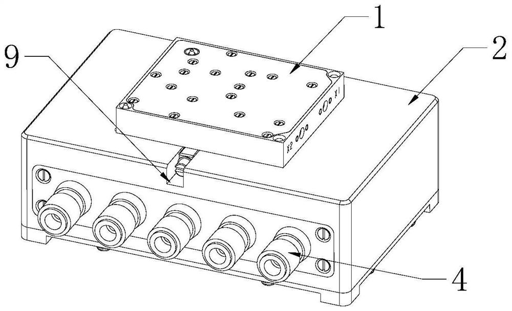
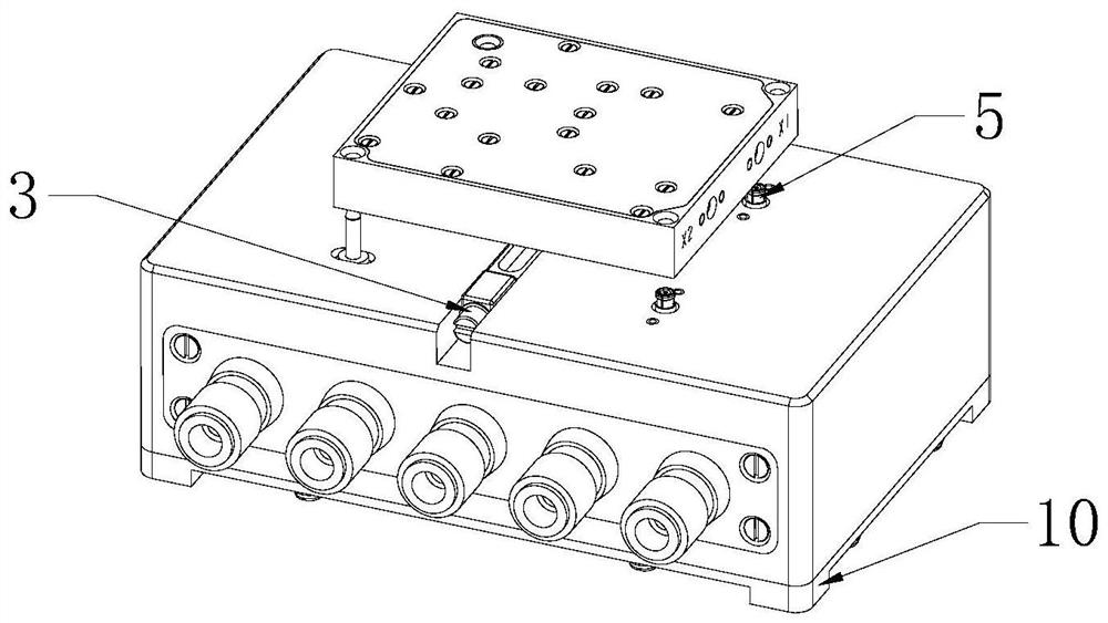
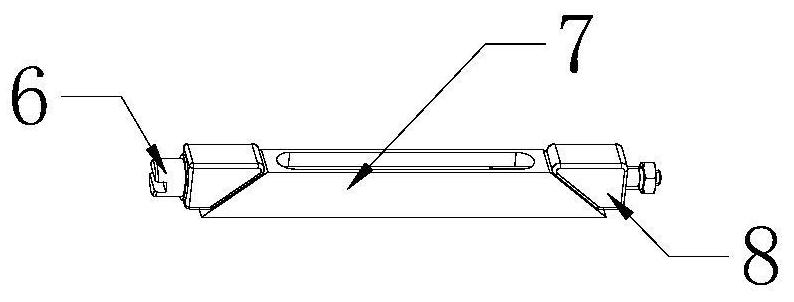
The invention provides a test tool and a manufacturing method thereof. The test tool comprises a shell with an accommodating cavity; the input and output connector is positioned in the accommodating cavity and is exposed from one side wall of the shell; the connector is positioned in the accommodating cavity and is exposed from the top wall of the shell; the connector is configured to be fixed with a connector on a product in a plugging manner; the shell comprises a clamping groove which is formed by inwards sinking the surface of the top wall of the shell; a wedge-shaped locking device is arranged in the clamping groove; the wedge-shaped locking device comprises a lifting part capable of moving in the vertical direction, and the wedge-shaped locking device is configured to enable the plug-in connector on the product to be separated from the plug-in connector through ascending of the lifting part. The test tool can avoid damage to the surface of the product in the process of pulling out the product.

Description

technical field [0001] The invention relates to the technical field of electronic testing equipment. More specifically, it relates to a test tool and a manufacturing method thereof. Background technique [0002] In the process of electronic module testing, it is often encountered that it is difficult to pull out the direct-push blind plug-in module. The common solution is to pry through the lever structure or with the help of tools such as screwdrivers. The lever method is used to save effort, but the volume is relatively large. , It is easy to scratch the surface of the module by prying with tools such as screwdrivers. Contents of the invention [0003] In view of the above problems, the present invention provides a test tool to solve the problem that the existing pulling structure easily scratches the surface of the product when pulling out the product. [0004] To achieve the above object, the present invention adopts the following technical solutions: [0005] The p...

Claims


Application Information

Patent Timeline
Patent Type & Authority Applications(China)
IPC IPC(8): H01R13/46H01R13/629G01R1/04
CPCH01R13/629H01R13/62933H01R13/46G01R1/0416
Inventor 雷恒宁熊尚威
Owner BEIJING INST OF RADIO MEASUREMENT
Learn More